

Tensile Young's modulus measuring instrument frictionless mouable platform
A movable platform, Young's modulus technology, applied in measuring devices, instruments, using stable tension/pressure to test the strength of materials, etc. The effect of accelerated experiment progress, easy adjustment, and improved measurement accuracy
- Summary
- Abstract
- Description
- Claims
- Application Information
AI Technical Summary
Problems solved by technology
Method used
Image

Examples
Embodiment Construction
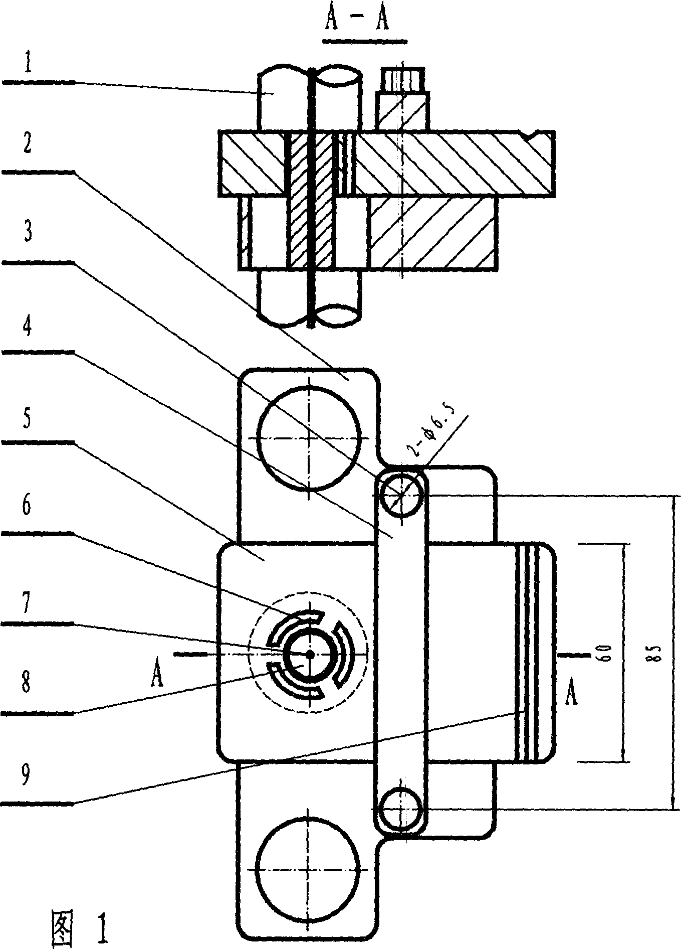
[0009] In Figure 1, the movable platform (5) is placed on the light lever support plate (2), and the movable chuck (8) fixed on the sample wire (7) to be tested is placed on the light lever support plate (2) and the movable platform at the same time In the middle hole of (5), the diameter of the middle hole of the light lever support plate (2) is 10-15mm larger than the outer diameter (or circumscribed circle) of the movable collet, and the diameter of the middle hole of the movable platform (5) is only larger than the outer diameter of the movable collet. (or circumscribed circle) is 1-2mm larger. The function of the viewing hole (6) is to facilitate the observation of whether the movable chuck is in contact with the middle hole wall of the light lever support plate (2). A small groove is machined in front of the movable platform (5). (9), so that the front foot of the plane mirror is located here, the pressure strip (4) is placed on the movable platform (5), and is connected ...
PUM
 Abstract
Description
Claims
Application Information