Filter

A filter device and filter layer technology, applied in the direction of filter separation, fixed filter elements, chemical instruments and methods, etc., can solve the problems of large flow water pumps, poor adaptability of filter materials, and low pollution capacity of filter layers, and achieve structural Simple, convenient installation, and the effect of extending the filtration cycle

Inactive Publication Date: 2006-11-01
TONGJI UNIV +1
View PDF0 Cites 6 Cited by
  • Summary
  • Abstract
  • Description
  • Claims
  • Application Information

AI Technical Summary

Problems solved by technology

[0010] The purpose of the present invention is to provide an improved filter device, which can overcome some deficiencies in the prior art, such as the low dirt-holding capacity of the filter layer, the need to configure a large-flow water pump and poor adaptability of the filter material.

Method used


Image

  • Filter
  • Filter
  • Filter

Examples


Embodiment 2

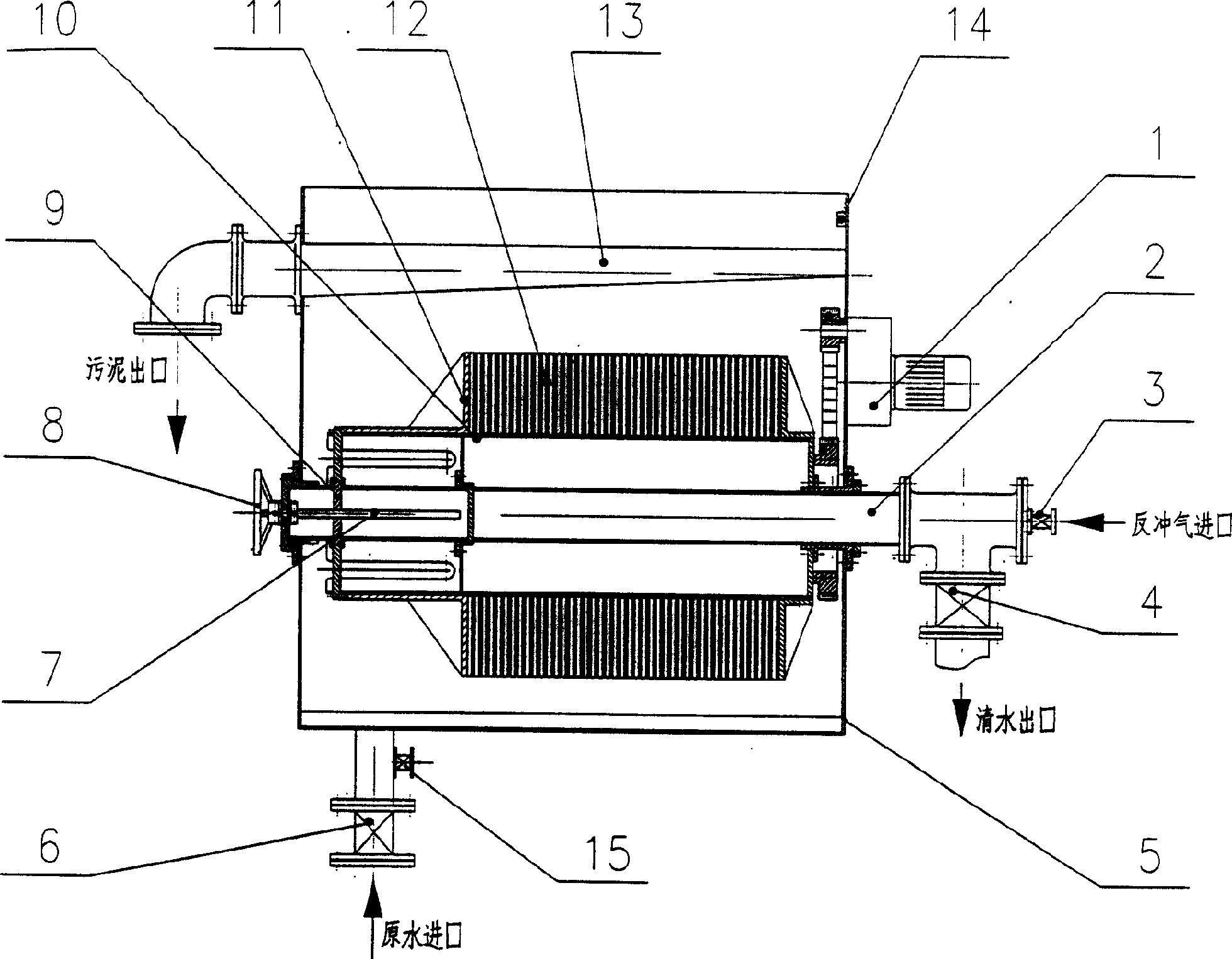
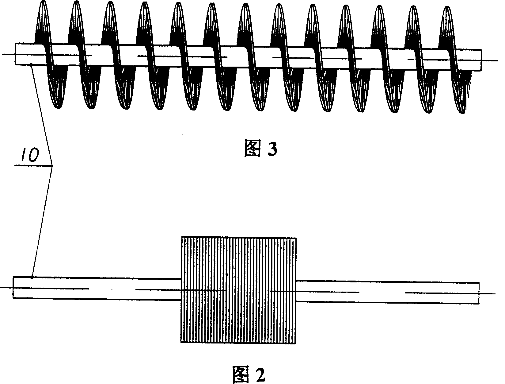
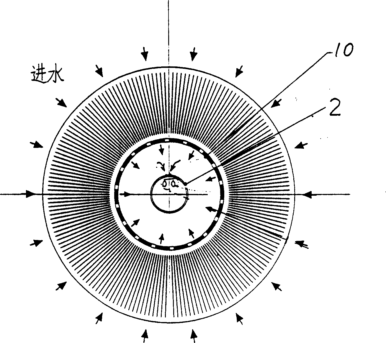
[0027] In embodiment 2, the filter device is a wheel-shaft structure, and the elastic fiber bundle is used as the filter layer to form the filter wheel 12. The lower end of the elastic fiber bundle is fixed on the drum 10, and the upper end is fixed with the slider 18, and the slider is sleeved on the radial slide rod 17. Above, 30 radial sliding rods are arranged in the radial direction and axial direction of the drum, and each radial sliding rod is responsible for the relaxation and compression of an elastic fiber bundle. When the slide block 18 tends toward the lower end of the radial slide bar, the elastic fiber bundle is in a compressed state, and the upper and lower ends of the radial slide bar are provided with upper and lower limit positions 19, 16 to control the degree of relaxation and compression of the elastic fiber bundle .

[0028] Raw water enters the shell 5 through the water inlet valve 6. At this time, the liquid level sensor does not detect the water level s...


PUM


Abstract

A filter for treating water is composed of a casing, a filtering drum consisting of a hollow central axle, a drum sleeving on said central axle and a filtering layer surrounding said drum and made of spiral strip plates or elastic fiber bundles, a reverse flushing air inlet at one end of said hollow central axle, and a speed reducer.

Description

Technical field: [0001] The invention relates to the technical field of filter devices in the water treatment industry, in particular to a filter device whose filter body is a filter wheel. Background technique: [0002] Since the emergence of natural slow filters, the form of filters has been constantly changing, such as ordinary fast filters, double valve filters, siphon filters, valveless filters, air-water backwash filters, etc. The changes are mainly carried out around three aspects: [0003] 1. Reduce the use of valves to save investment and reduce operating links; such as changing from a four-valve filter to a double-valve and no-valve filter. [0004] 2. Change the type and combination of filter materials to improve the ability of filter materials to intercept sewage and improve the quality of effluent water, such as using white coal, ceramsite, plastic particles, and combinations of different particle sizes. [0005] 3. Save backwashing water, reduce water pressur...

Claims


Application Information

Patent Timeline
Patent Type & Authority Applications(China)
IPC IPC(8): B01D29/44B01D29/48
Inventor 赵建夫张亚雷吴勇陈翼孙黄永宽崔程颖
Owner TONGJI UNIV
Why Eureka
Try Eureka