Labyrinth sealing structure of industrial labyrinth compressor

A labyrinth seal, compressor technology, applied in mechanical equipment, machines/engines, liquid variable-capacity machinery, etc., can solve the problem of increasing compressor maintenance workload and operating costs, environmental pollution of separation and drainage, and large consumption of lubricating oil. and other problems, to achieve the effect of reducing unplanned downtime, reducing maintenance workload, and reducing the number of spare parts

Inactive Publication Date: 2006-11-01
WUXI COMPRESSOR CO LTD +1
View PDF0 Cites 4 Cited by
  • Summary
  • Abstract
  • Description
  • Claims
  • Application Information

AI Technical Summary

Problems solved by technology

In order to reduce friction and wear, lubricating oil is injected on the contact surface, and the injection of oil pollutes the compressed medium and consumes a large amount of lubricating oil, and the separation and drainage of oil also pollutes the environment
At present, although a self-lubricating material is widely used to manufacture piston rings and sealing rings, and lubricating oil is cancelled, the wear caused by contact friction still exists.
Piston rings and sealing rings are vulnerable parts and must be replaced regularly, which increases the maintenance workload and operating costs of the compressor. At the same time, ...

Method used


Image

  • Labyrinth sealing structure of industrial labyrinth compressor
  • Labyrinth sealing structure of industrial labyrinth compressor

Examples


Embodiment Construction

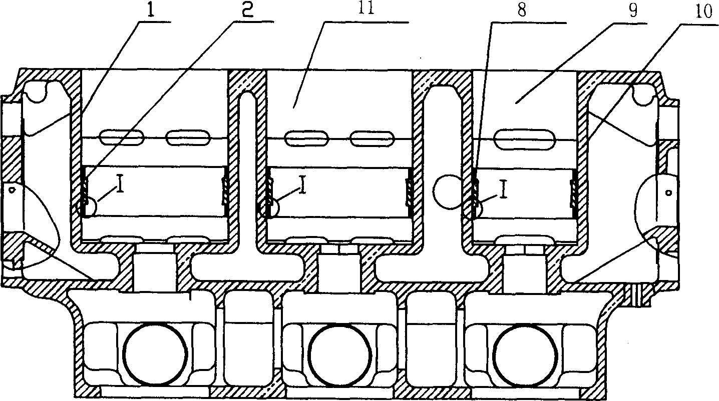
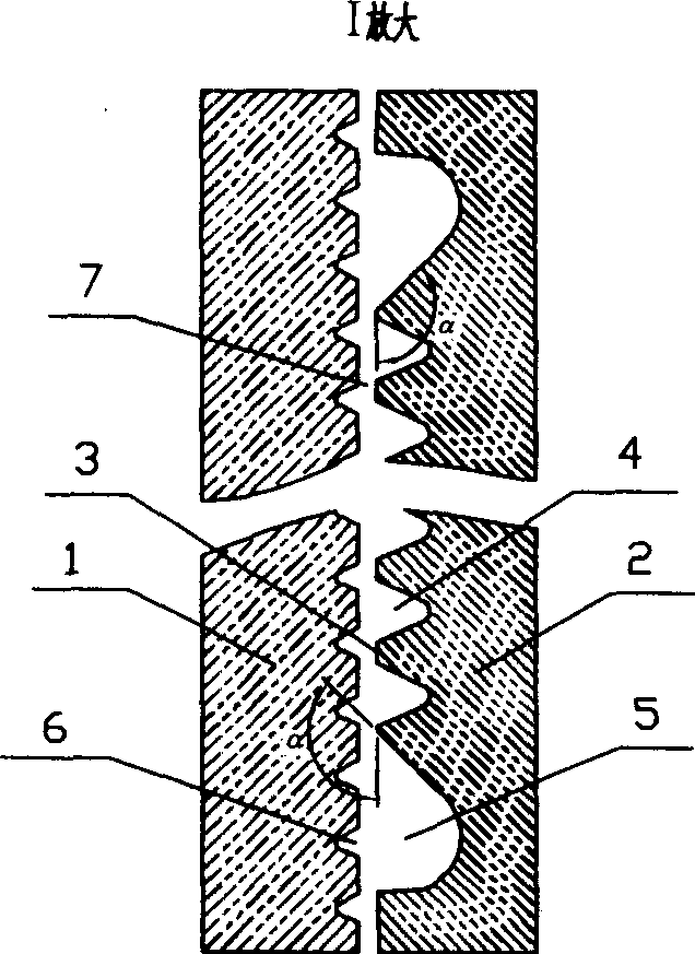
[0010] The present invention will be described in further detail below in conjunction with the accompanying drawings.

[0011] combine figure 1 , figure 2 , the present invention comprises a cylinder block, in which a cylinder chamber and a piston jacket 2 are arranged, and cylinder walls 1 are formed on both sides of the cylinder chamber 11, a labyrinth groove volume chamber is arranged on the cylinder wall 1, and a throttling point 3 is arranged on the piston jacket 2 , the volume chamber 4, the piston jacket 2 is separated from the cylinder wall 1 to form a small gap 7, the large three-row two-stage compression labyrinth compressor consists of two primary cylinder chambers 11 and a secondary cylinder chamber 9, when the primary piston When moving downward, the volume of the first-stage cylinder becomes larger, the first-stage intake valve opens, and the compressed gas enters the cylinder. When the piston moves upward, the piston works, the volume of the cylinder becomes s...


PUM


Abstract

The invention comprises an air cylinder, are disposed in which an air cylinder cavity and a piston jacket. On both sides of the air cylinder cavity there are air cylinder walls, on which is disposed a labyrinth groove volume room and on the piston jacket are disposed throttle port and a volume room. The piston jacket and the air cylinder walls are separated to form small gaps.

Description

A technical field [0001] The invention relates to a structure of an industrial compressor, in particular to a labyrinth sealing structure of an industrial labyrinth compressor. Two background technology [0002] Piston compressors are general-purpose machinery widely used in various industries. In order to effectively compress the medium gas, the traditional piston compressor works by the reciprocating motion between the piston ring on the piston and the cylinder, as well as the piston rod and the sealing ring in the packing. The relative movement in contact with each other creates friction and material wear. In order to reduce friction and wear, lubricating oil is injected on the contact surface, and the injection of oil pollutes the compressed medium and consumes a large amount of lubricating oil, and the separation and drainage of oil also pollutes the environment. At present, although a self-lubricating material is widely used to manufacture piston rings and sealing ri...

Claims


Application Information

Patent Timeline
IPC IPC(8): F04B39/00F04B27/12F04B53/02
Inventor 朱建明戴晓洲钱林方吴文莉赵彦滨
Owner WUXI COMPRESSOR CO LTD
Why Eureka
Try Eureka