
Light projection lens structure

A lens structure and projection technology, which is applied in the direction of instruments, lighting and heating equipment, fixed lighting devices, etc., can solve the problems of difficult mass production, difficult structure volume, time-consuming and labor-intensive, etc.

Inactive Publication Date: 2006-11-01
T Y C BROTHER IND CO LTD
View PDF0 Cites 3 Cited by
  • Summary
  • Abstract
  • Description
  • Claims
  • Application Information

AI Technical Summary

Problems solved by technology

[0002] Prior art projective lens structure (such as Figure 5 As shown), glass lens A is used, and the mold for forming glass lens A has high temperature resistance requirements and rapid wear and tear, and the molded product must also be ground, which is quite time-consuming and labor-intensive, and it is more difficult to produce in large quantities. cost; moreover, the glass lens A cannot be recycled and reused, which invisibly increases waste production
[0003] The weight of the glass lens A of this lens structure accounts for about 40% to 60% of the overall lens structure. Therefore, if the glass lens A is used in a car light, it is very easy to cause the center of gravity of the lens structure to be forward, thus causing the deformation of the reflector, and The load of the adjustment mechanism of the lens structure is increased, and the service life of the relative structure is reduced, especially the adaptive front lighting system (Adaptive Front-lighting System, AFS). The problem to be solved is urgent

Method used


Image

  • Light projection lens structure
  • Light projection lens structure
  • Light projection lens structure

Examples


Embodiment Construction

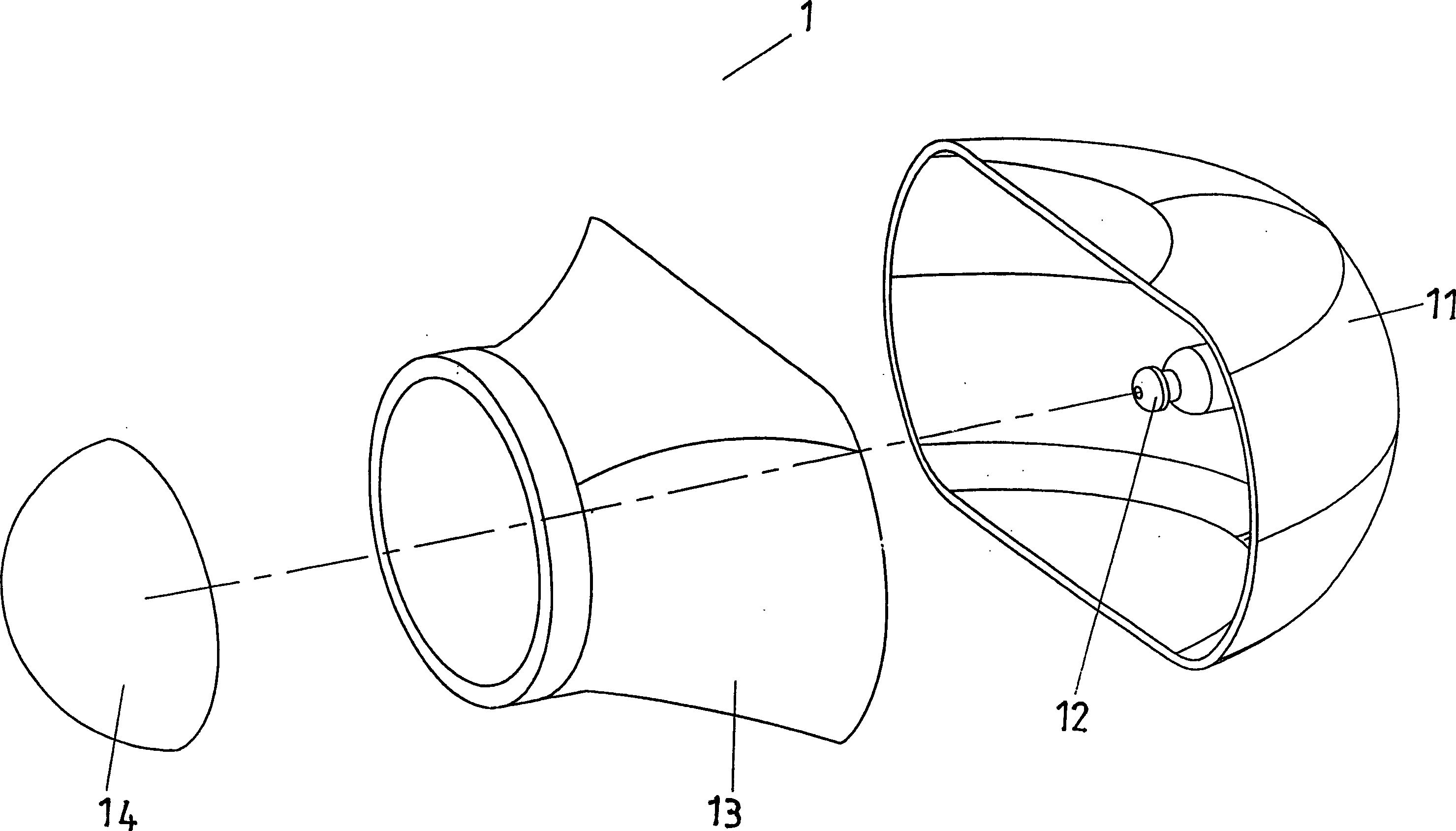
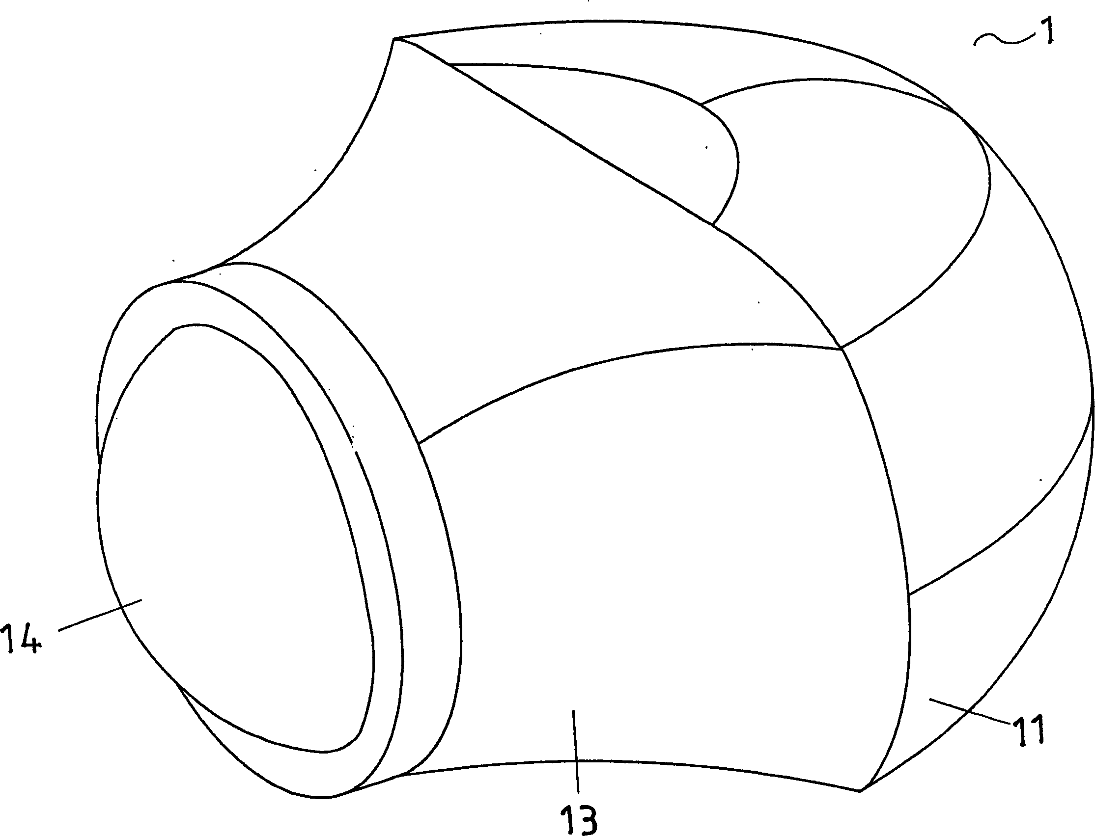
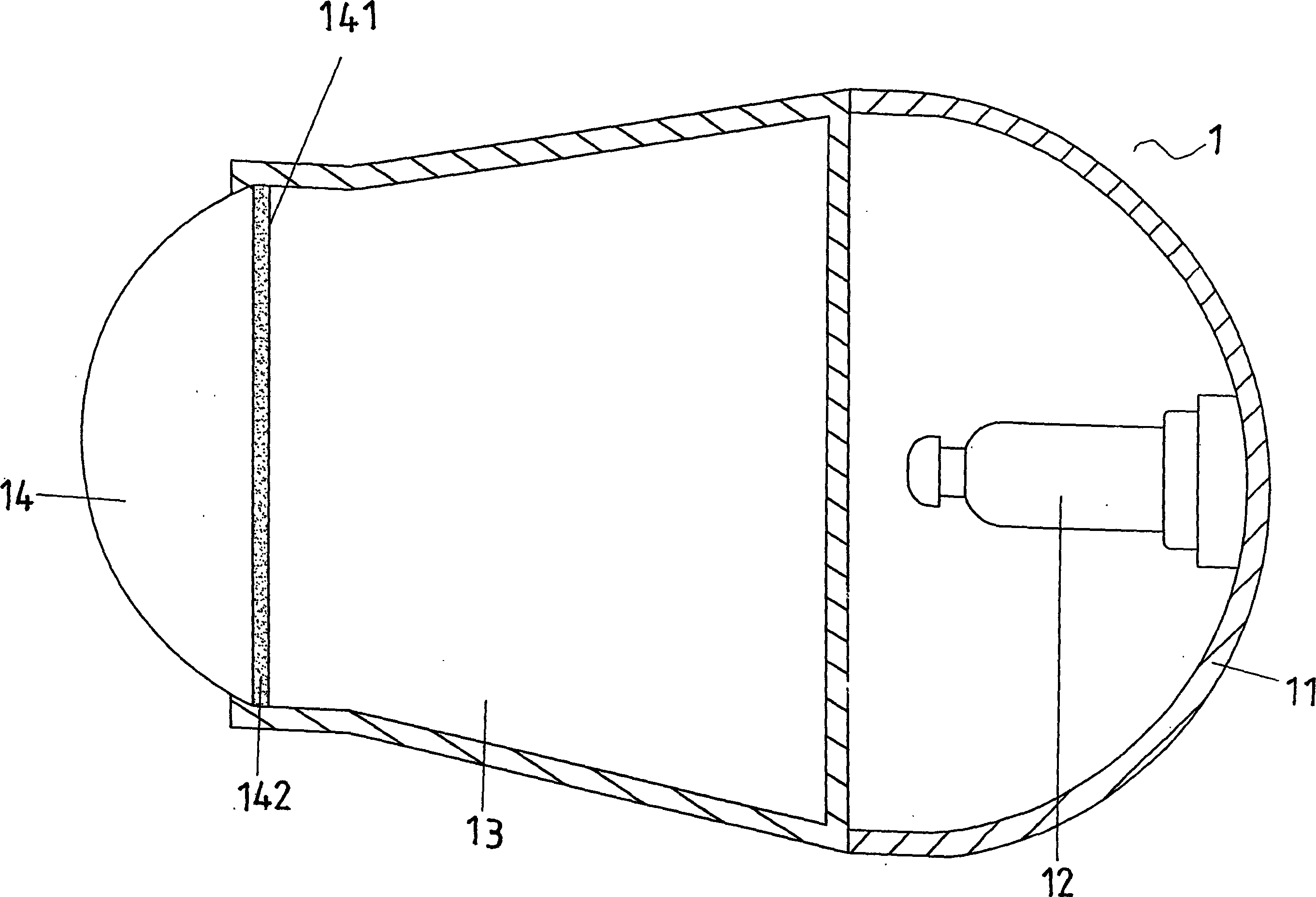
[0013] Such as figure 1 , figure 2 As shown, it is a schematic diagram of an embodiment of the light-weight projection lens structure of the present invention applied to a car lamp. The lens structure 1 is mainly connected to a light source 12 inside a reflector 11, and supports are successively assembled on the reflector 11. Body 13 and a lens body 14.

[0014] Such as image 3 As shown, the lens body 14 of the lens structure 1 is a light-condensing light-transmitting body, which is made of heat-resistant and yellow-resistant optical plastic material, and an inorganic oxide is coated on the light-entry surface 141 of the lens body 14. Thin film coating 142 persons.

[0015] Such as Figure 4 , Figure 5 As shown, because the lens body 14 of the lens structure 1 is made of optical plastic material and coated with a coating 142 , it can also achieve the same light projection effect as the glass lens A in the prior art.

[0016] Due to the design of the present invention,...


PUM


Abstract

A light and projective lens consists of a reflection body, a light source, a support body and a lens body. It is featured as setting lens body to be a focusing light transmission body made of optical plastic material with heat proof and changing to be yellow color proof property, coating a layer of inorganic oxide film on lens body for isolating infrared and ultraviolet ray, utilizing ejection process to prepare optical plastic lens body for saving grinding process used in preparing normal lens body so as to be easy to produce large amount of optical plastic lens body.

Description

technical field [0001] The invention relates to a light-weight projection lens structure, in particular to a lens body made of optical plastic to block infrared rays and ultraviolet rays by coating technology. Background technique [0002] Prior art projective lens structure (such as Figure 5 As shown), glass lens A is used, and the mold for forming glass lens A has high temperature resistance requirements and rapid wear and tear, and the molded product must also be ground, which is quite time-consuming and labor-intensive, and it is more difficult to produce in large quantities. cost; moreover, the glass lens A cannot be recycled and reused, which invisibly increases waste production. [0003] The weight of the glass lens A of this lens structure accounts for about 40% to 60% of the overall lens structure. Therefore, if the glass lens A is used in a car light, it is very easy to cause the center of gravity of the lens structure to be forward, thus causing the deformation o...

Claims


Application Information

Patent Timeline
Patent Type & Authority Applications(China)
IPC IPC(8): G02B1/04F21S8/10
Inventor 黄競贤吴享珍
Owner T Y C BROTHER IND CO LTD
Learn More