Passive multilevel wave filter

A polyphase filter, passive type technology, applied in multi-terminal pair network, semiconductor/solid-state device manufacturing, electrical components, etc., can solve the problems of different relative deviations and difficulty in obtaining resistance values, etc.

Inactive Publication Date: 2006-11-01
コラボイノベーションズインコーポレイテッド
View PDF1 Cites 1 Cited by
  • Summary
  • Abstract
  • Description
  • Claims
  • Application Information

AI Technical Summary

Problems solved by technology

[0009] On the other hand, in Figure 22 In the configuration of such a 4-phase input passive polyphase filter, since the directions of the resistor R1 and the resistor R3, and the resistor R4 and the resistor R2 are different, the relative deviation is different, and

Method used


Image

  • Passive multilevel wave filter
  • Passive multilevel wave filter
  • Passive multilevel wave filter

Examples


Embodiment approach 1

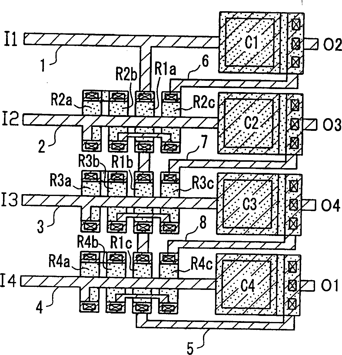
[0052] figure 1 A layout diagram showing a passive polyphase filter according to the first embodiment. This configuration is implemented with Figure 20 The configuration of the circuit structure of the 4-phase input passive type polyphase filter. for with Figure 21 , Figure 22 The same reference numerals will be assigned to the same elements as those in the conventional example, and will be described.

[0053] exist figure 1 In the configuration of the Figure 20 Resistors R1-R4 are respectively divided into three to form a set of partial resistors. That is, resistor R1 is composed of partial resistors R1a-R1c, resistor R2 is composed of partial resistors R2a-R2c, resistor R3 is composed of partial resistors R3a-R3c, and resistor R4 is composed of partial resistors R4a-R4c. As will be apparent from the embodiments described later, in the present invention, m resistors are divided into (m−1) or more partial resistors. In addition, although not shown in figure, in the...

Embodiment approach 2

[0066] Image 6 It is a circuit diagram of the 3-phase input passive type polyphase filter of Embodiment 2. The resistors R1-R3 and the capacitors C1-C3 are connected in a ring shape, and have input terminals I1-I3 and output terminals O1-O3. Figure 7 yes means Image 6 A layout diagram showing the arrangement of each element of the 3-phase input passive type polyphase filter shown. The circuit configuration and the arrangement of each element are basically the same as those in Embodiment 1, and the same reference numerals are assigned to the same elements, and description thereof will be omitted.

[0067] Such as Figure 7 As shown, will Image 6 Resistors R1~R3 ​​are divided into two to form a set of partial resistors. Resistor R1 is composed of partial resistors R1a~R1b, resistor R2 is composed of partial resistors R2a~R2b, and resistor R3 is composed of partial resistors R3a~R3b. Group composition. Resistors R2 to R3 are arranged by combining partial resistors R2a t...

Embodiment approach 3

[0073] Figure 10 It is a circuit diagram of the 5-phase input passive type polyphase filter of Embodiment 3. The resistors R1-R5 and the capacitors C1-C5 are connected in a ring shape, and have input terminals I1-I5 and output terminals O1-O5. Figure 11 yes means Figure 10 A layout diagram showing the arrangement of each element of the 5-phase input passive type polyphase filter shown. The circuit configuration and the arrangement of each element are basically the same as those in Embodiment 1, and the same reference numerals are assigned to the same elements, and description thereof will be omitted.

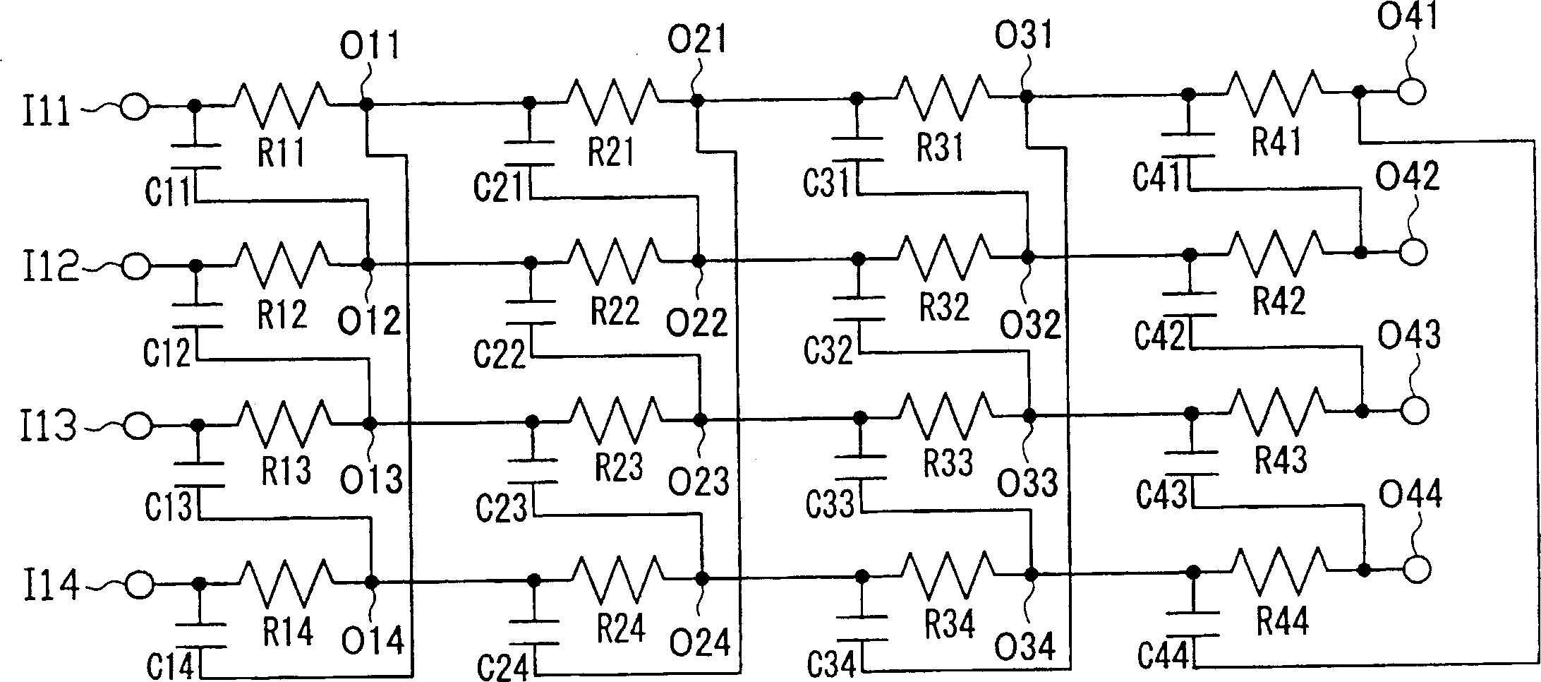
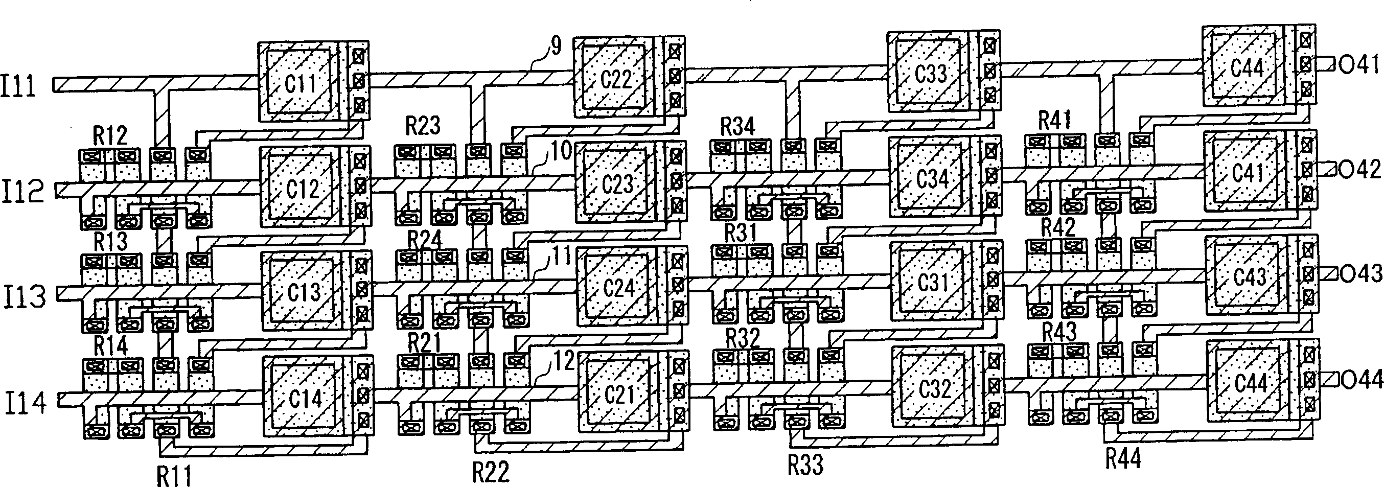
[0074] As an application example of the configuration of the present embodiment described above, Figure 12 The circuit diagram of a three-stage 5-phase input passive polyphase filter is shown in . For the first stage filter composed of resistors R11~R15 and capacitors C11~C15, the second stage filter composed of resistors R21~R25 and capacitors C21~C25 is connected to th...


PUM


Abstract

Four input nodes for inputting 4-phase signals, four resistors, four capacitors, and four output nodes for outputting 4-phase signals are provided. The resistors and the capacitors are connected alternately in a loop, and the input nodes and output nodes are connected alternately to the respective nodes between the resistors and the capacitors sequentially. Each of the four resistors is composed of a group of three or more partial resistors, and three groups of the partial resistors are collected respectively and arranged in the same attitude, while the partial resistors of the remaining group are distributed into the other groups and arranged in the same line the same attitude as the partial resistors of each of the other groups. The regions of the thus collected groups are arranged in one direction. By simplifying the layout of the components and the shape of the wirings, influences on the characteristics by the parasitic elements are reduced, and complication in the layout and wirings can be suppressed even when using plural stages.

Description

technical field [0001] The present invention relates to a passive polyphase filter (complex filter) used for image suppression in signal processing of electronic equipment, and in particular to improvements in arrangement of resistors, capacitors, and input / output terminals as constituent elements. Background technique [0002] Passive type polyphase filters used in image suppression, etc. in signal processing of electronic equipment, for example, in the case of 4-phase input, have such Figure 20 The circuit configuration shown. Connect resistors R1, R2, R3, R4 and capacitors C1, C2, C3, C4 in a ring to form Figure 20 The passive polyphase filter, I1, I2, I3, I4 are the input terminals of the input signal, O1, O2, O3, O4 are the output terminals of the output signal. Resistors R1 to R4 have the same resistance value, and capacitors C1 to C4 have the same capacitance value. [0003] exist Figure 20 In the circuit, as the signal processing from the input terminal I1 to the...

Claims


Application Information

Patent Timeline
IPC IPC(8): H03H7/00H01L21/822
Inventor 小笹正之横山明夫大久保学空元孝夫
Owner コラボイノベーションズインコーポレイテッド
Why Eureka
Try Eureka