
Head unit, electrospinning head, and electrospinning apparatus

A technology of electrospinning and nozzles, which is applied in the directions of spinneret assemblies, textile and papermaking, filament/thread forming, etc., can solve the problems of complication of restraint structure and control system, reduction of productivity, increase of manufacturing cost, etc. The effect of suppressing the complexity of the structure and control system

Active Publication Date: 2020-09-22
KK TOSHIBA
View PDF7 Cites 1 Cited by
  • Summary
  • Abstract
  • Description
  • Claims
  • Application Information

AI Technical Summary

Problems solved by technology

In addition, in the electrospinning device, it is required to suppress the complexity of the structure and the control system, and at the same time, it is required to suppress the increase in the manufacturing cost of the electrospinning nozzle and the reduction in productivity.

Method used


Image

  • Head unit, electrospinning head, and electrospinning apparatus
  • Head unit, electrospinning head, and electrospinning apparatus
  • Head unit, electrospinning head, and electrospinning apparatus

Examples


no. 1 approach

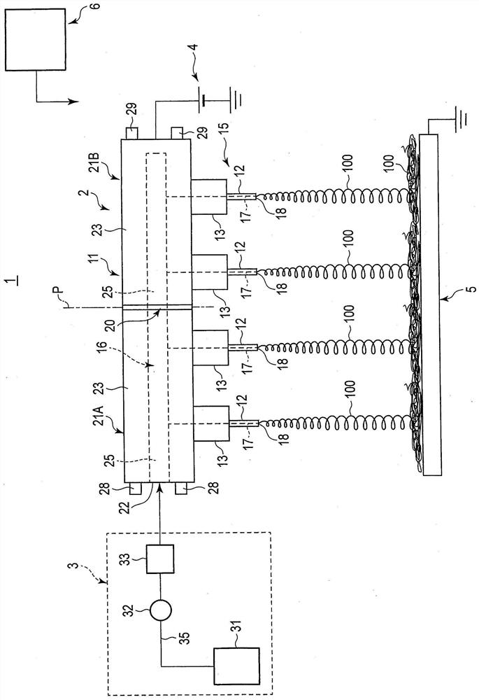
[0025] figure 1 An example of the electrospinning device 1 according to the first embodiment is shown. Such as figure 1 As shown, the electrospinning device 1 includes an electrospinning nozzle 2, a supply source (supply part) 3 of a raw material liquid, a power source 4, a collector 5, and a control part 6.

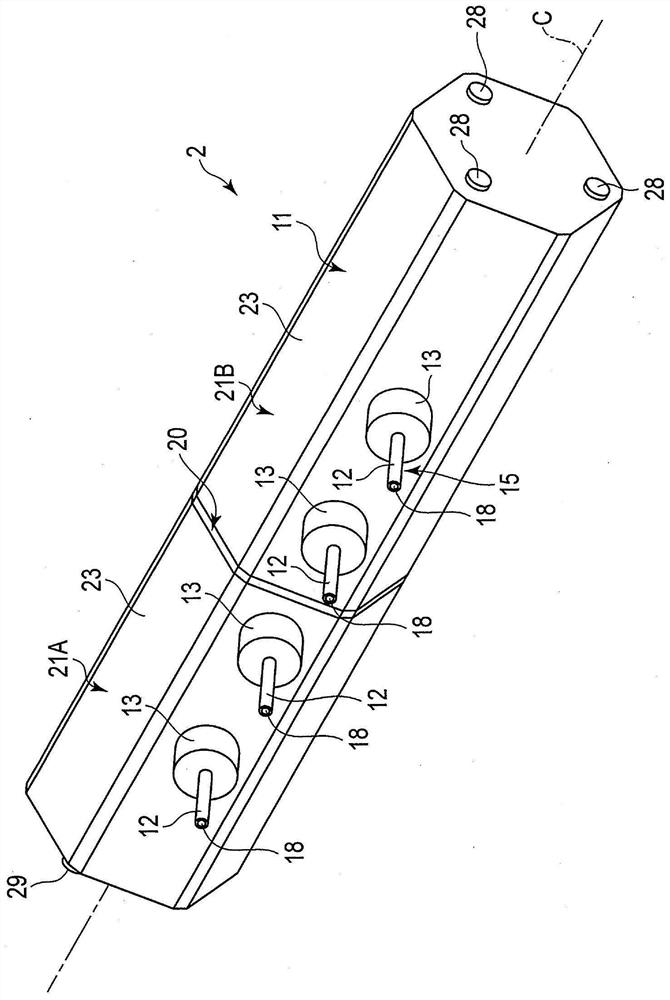
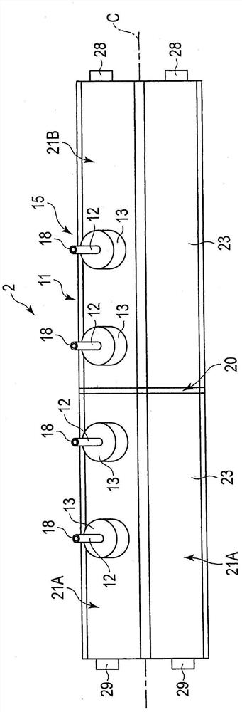
[0026] Figure 2 to Figure 5 Shows the structure of the electrospinning nozzle 2. Such as Figure 1 to Figure 5 As shown, the electrospinning nozzle 2 has a long side axis C as a central axis, and is arranged to extend along the long side axis C. The electrospinning nozzle 2 includes a nozzle body 11 and a plurality of (four in this embodiment) nozzles 12. In addition, the electrospinning nozzle 2 is provided with the same number of connection parts 13 as the nozzles 12, and the nozzles 12 are respectively connected to the nozzle body 11 via a corresponding one of the connection parts 13. In this embodiment, the shower head body 11, the nozzle 12, and the connection porti...


PUM


Abstract

The embodiment of the invention relates to a head unit, an electrospinning head and an electrospinning apparatus, and provides a head unit, an electrospinning head and an electrospinning apparatus which are capable of inhibiting a structure, controlling the complexity of the control system, the increasing of the manufacturing cost and reducing the production rate and properly forming the film of afiber with a large size in the width direction. According to the embodiment, the electrospinning head comprises a plurality of head units and a coupling structure, and the plurality of head units arecoupled to one another through the coupling structure. Each head unit includes a unit main body and a nozzle. Inside the unit main body, a hollow storing a raw material liquid is formed along a longitudinal axis. The nozzle is formed of a conductive material and provided on an outer circumferential surface of the unit main body. The nozzle ejects the raw material liquid supplied through the hollow of the unit main body. The coupling structure connects the plurality of head units in a state where the hollows of the unit main bodies communicate with one another.

Description

Technical field [0001] The embodiment of the present invention relates to a nozzle unit, an electrospinning nozzle, and an electrospinning device. Background technique [0002] There is an electrospinning device in which fine fibers are deposited on the surface of a collector or a substrate by an electrospinning method (sometimes called an electrospinning method or a charge induction spinning method) to form a fiber membrane. The electrospinning device is provided with an electrospinning nozzle having a nozzle body and nozzles. In the electrospinning nozzle, a cavity (head flow path) for accommodating the raw material liquid is provided inside the nozzle body, and nozzles are provided on the outer peripheral surface of the nozzle body. Furthermore, by applying a voltage between the electrospinning nozzle and the collector or the substrate, the raw material liquid is ejected from the nozzle outlet toward the surface of the collector or the substrate, and the fibers are deposited ...

Claims


Application Information

Patent Timeline
Patent Type & Authority Applications(China)
IPC IPC(8): D01D5/00
CPCD01D5/0069D04H1/728D01D5/0076D01D4/06D01D13/00
Inventor 木下静雄小林浩秋内田健哉町田守宽
Owner KK TOSHIBA
Learn More