False-twisting device

A technology of false twisting and friction discs, which is applied in the direction of textiles and papermaking, and can solve problems such as increased tension, small engagement angle, and reduced twisting component force

Inactive Publication Date: 2006-11-01
SAURER GMBH & CO KG
View PDF3 Cites 6 Cited by
  • Summary
  • Abstract
  • Description
  • Claims
  • Application Information

AI Technical Summary

Problems solved by technology

With the proposed flatter engagement angle, the contact length between the wire and the circumferential surface of the friction disc is increased, so that this friction situation leads to an increase in the tensile force, however, it is very disadvantageous that the force component used to generate the twist reduced
This disadvantage is further exacerbated by the selection of the largest possible profile radius in the range of 6.5 to 8 mm in proportion to the disc width of the friction disc, which necessarily leads to a small engagement angle

Method used


Image

  • False-twisting device
  • False-twisting device
  • False-twisting device

Examples


Embodiment Construction

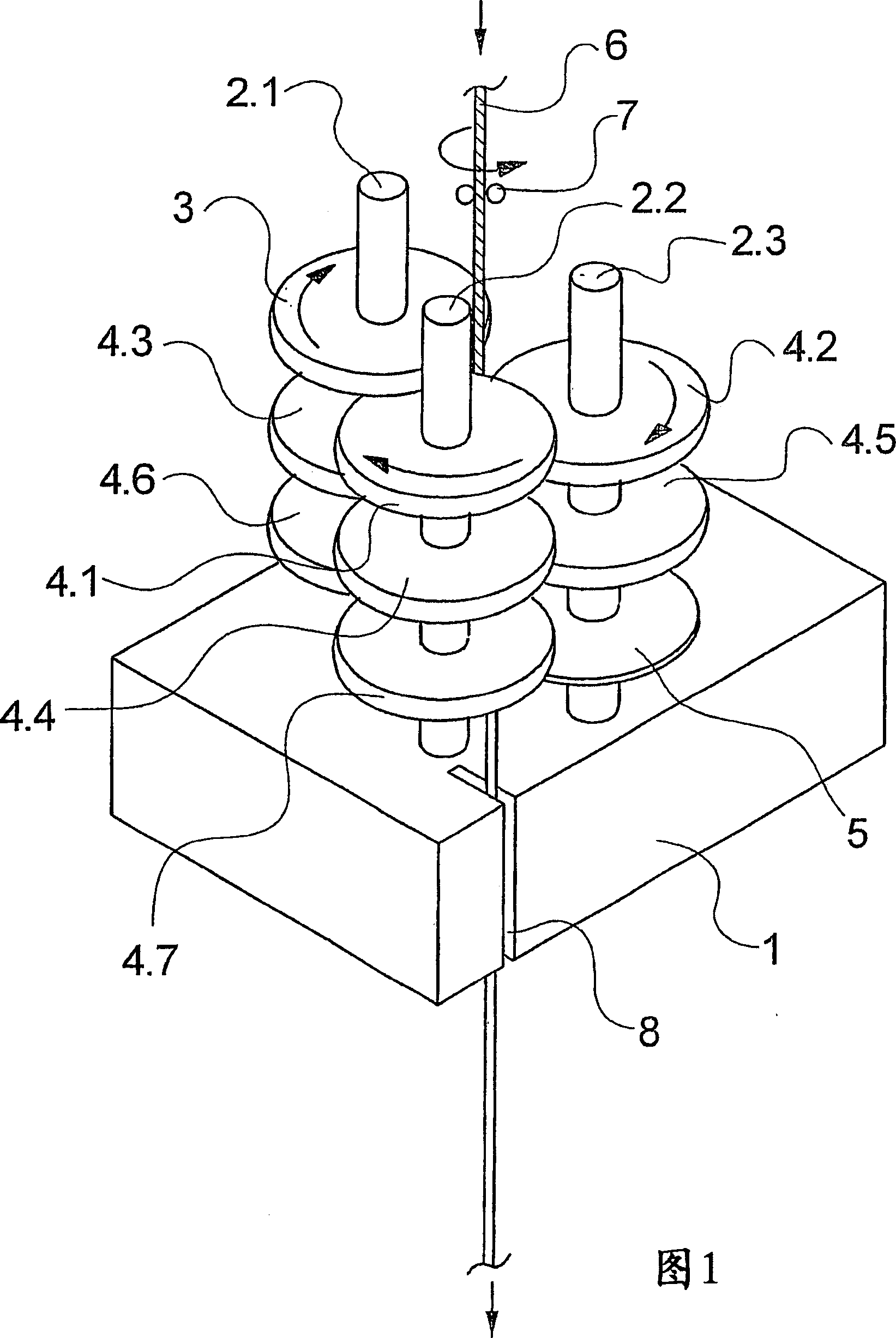
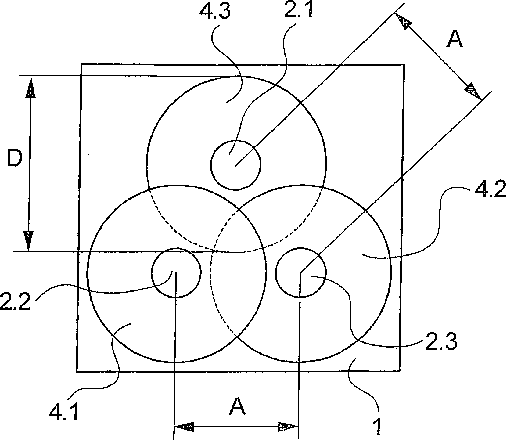
[0022] In Figure 1 and figure 2 A first embodiment of the false twisting device of the present invention is schematically shown in . Fig. 1 is the perspective view of false twist device, figure 2 It is a top view of the false twisting device. The following description applies to both figures, unless one of them is explicitly referenced.

[0023] The false twisting device has a support base 1 . A plurality of shafts 2.1, 2.2 and 2.3 are rotatably mounted on the bearing 1 in a protruding manner. The shafts 2.1, 2.2 and 2.3 are coupled at their bearing ends to a drive (not shown here). A drive of this type is known, for example, from EP 0 7444 80 A1. In this respect, the contents of the cited documents are all incorporated by reference.

[0024] The axes 2.1, 2.2 and 2.3 are arranged in a triangle. A plurality of friction disks 4.1 to 4.7 offset from one another are arranged on the shafts 2.1, 2.2 and 2.3. Specifically, the shaft 2.1 has an input disc 3 and two friction d...


PUM

PropertyMeasurementUnit
diameteraaaaaaaaaa

Abstract

Disclosed is a device for false-twisting a synthetic thread, comprising several shafts that are rotatably mounted on a bearing block. Said shafts are arranged at a respective axial distance from each other so as to form a triangle. Several friction disks are mounted on the shafts so as to be offset relative to each other. The friction disks have a diameter that is large enough for the friction disks to overlap in the center of the triangle while the circumferential surfaces thereof form a wound thread course. In order to lower the thread tension at high production speeds while obtaining a great twisting effect, the degree of overlapping of the friction disks is determined by a ratio between the disk diameter and the axial distance, which is >1.45, the friction disks having a width ranging between 9.5 mm and 11.5 mm.

Description

technical field [0001] The invention relates to a false twisting device for false twisting synthetic yarns according to the preamble of claim 1 . Background technique [0002] In the production of crimped textile threads, it is known to impart a false twist to the thread by friction, which is fixed in the thread filaments by heat treatment in the region of the crimp deformation. For forming the false twist, in particular false twist devices in which the thread is guided along the circumferential surfaces of rotating, overlapping friction disks have proven to be very successful. A false twist device of this type is known, for example, from EP 0 943 022 B1. [0003] In known false twisting devices, the friction disks are arranged on three shafts which are rotatably mounted on a bearing support. The shafts are arranged at a distance from each other in a triangle, and the friction disks overlap at the center of the triangle. The shafts are driven via a transmission in such a ...

Claims


Application Information

Patent Timeline
Patent Type & Authority Applications(China)
IPC IPC(8): D02G1/08D02G1/04
CPCD02G1/082D02G1/06
Inventor F·布劳洛克
Owner SAURER GMBH & CO KG
Why Eureka
Try Eureka