Touching control device and control panel for household electric appliance

A technology for control devices and household appliances, which is applied in the direction of electronic switches, electrical components, electrical equipment shells/cabinets/drawers, etc., which can solve the problems of high equipment costs and waste of components, and reduce purchase costs, reduce quantities, and save purchase costs Effect

Inactive Publication Date: 2006-11-08
HAIER GRP CORP +1
View PDF0 Cites 4 Cited by
  • Summary
  • Abstract
  • Description
  • Claims
  • Application Information

AI Technical Summary

Problems solved by technology

[0003] However, in the current touch control device, each touch button corresponds to a packaging module, so each time a touch button is added, a corresponding packaging module needs to be added, and when the components in a certain packaging module are damaged, only Re-purchasing the entire packaging module causes waste of components and leads to higher equipment costs

Method used


Image

  • Touching control device and control panel for household electric appliance
  • Touching control device and control panel for household electric appliance

Examples


no. 1 example

[0028] Embodiment 1: The control panel of the refrigerator includes a display device and a touch control device, and the two are electrically connected through solder joints on a printed circuit board. There are three display units on the display device, which are respectively used to display the temperature of the refrigerating room, the temperature changing room and the freezing room, figure 1 A schematic diagram of the corresponding control device. Correspondingly, the touch control device includes a touch button 11 for controlling the temperature of the refrigerating room, the touch button 12 of the variable temperature room, and the temperature of the freezing room respectively. In this embodiment, each touch button corresponds to a sensor chip, the sensor chip 17 corresponding to the touch button 11, the sensor chip 27 corresponding to the touch button 21, and the sensor chip 27 corresponding to the touch button 31. Induction chip 37 . Each touch button of the control ...

no. 2 example

[0029] The second embodiment: a prominent advantage of the present invention is that the split sensor chip can realize a one-to-many structure with the touch button, and the refrigerator is still taken as an example to describe in detail below.

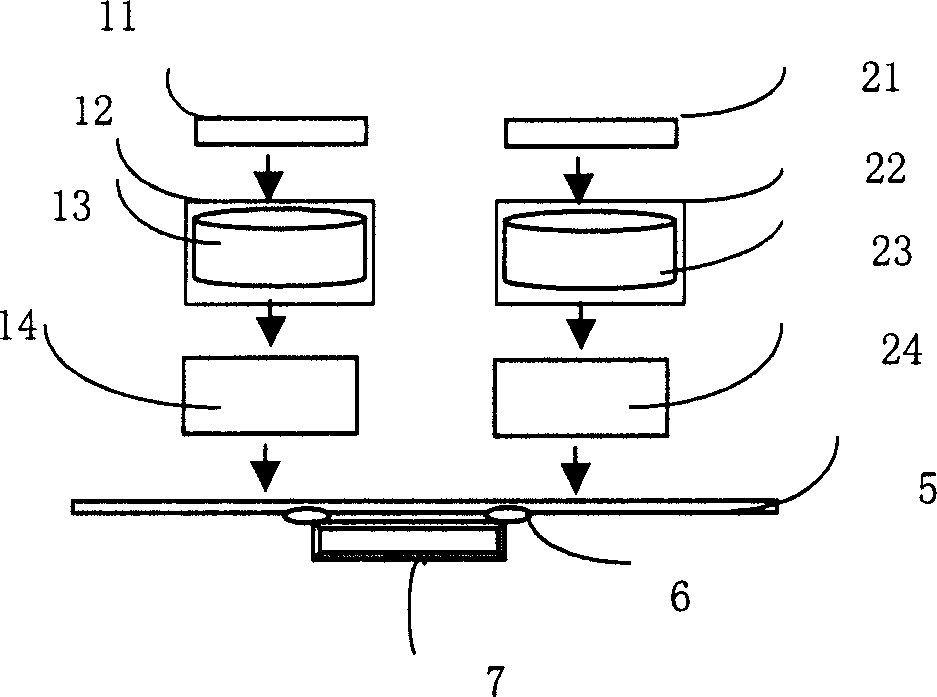
[0030] The control panel of the refrigerator includes a display device and a touch control device, and the two are electrically connected through solder joints on a printed circuit board. The display device includes three display units, which are respectively used to display the temperature of the refrigerating room, the temperature changing room and the freezing room, and are adapted to it. button. figure 2 It shows a structural diagram of using one sensing chip together with two touch buttons. On the front of the printed circuit board 5 are placed conductor cottons 12 and 22 , and fixing clips 13 and 23 for fixing the conductor cottons 12 and 22 , and brackets 14 , 24 and 34 are placed below each conductor cotton. In this embodim...


PUM


Abstract

This invention provides a touch control device of family appliances including an inducing chip at the PCB of the control device, a touch button connected with the chip, in which, said chip and the button are split structures. This invention also provides a control panel for family appliances including a display device at the PCB, an inducing chip and a touch button connected with the chip, both of which are split structures.

Description

technical field [0001] The invention relates to a household appliance, in particular to a touch control device and a control panel of the household appliance. Background technique [0002] The existing touch control devices for household appliances adopt a modular structure design, that is, the manufacturer packages the touch buttons, induction chips and related peripheral circuits, and the user welds the packaging module on the printed circuit board to form a touch control device. The structure of the current control panel is made by connecting a display device with the control device through a printed circuit board. [0003] However, in the current touch control device, each touch button corresponds to a packaging module, so each time a touch button is added, a corresponding packaging module needs to be added, and when the components in a certain packaging module are damaged, only Repurchasing the entire packaging module results in waste of components, resulting in higher...

Claims


Application Information

Patent Timeline
Patent Type & Authority Applications(China)
IPC IPC(8): H03K17/96H05K5/00
Inventor 李莉蒋国伟范纪青陈也夫朱旬
Owner HAIER GRP CORP
Why Eureka
Try Eureka