Method for cleaning liquid ejection apparatus and liquid ejection apparatus

A technology of jetting device and liquid jetting head, applied in printing and other directions, can solve the problems of increased ink consumption, high cost, complex structure, etc.

Inactive Publication Date: 2006-11-15
SEIKO EPSON CORP
View PDF2 Cites 18 Cited by
  • Summary
  • Abstract
  • Description
  • Claims
  • Application Information

AI Technical Summary

Problems solved by technology

[0008] However, in Japanese Patent Laid-Open No. 2004-174766, in order to remove accumulated ink, new ink must be sucked from the recording head with a suction pump, and ink consumption increases, resulting in high cost.
Moreover, when the removal device, etc., disclosed in JP-A-2004-167945 is installed in the waste liquid tank, the installation space of the removal device, etc. increases, and the waste liquid tank becomes larger. Assembled in the waste liquid tank, the structure becomes complicated
[0009] Although the inkjet printer was cited above, the same disadvantages as above also occur in other liquid ejection devices that use a liquid ejection head to eject liquid droplets, such as a display manufacturing device, an electrode forming device, or the above-mentioned biochip manufacturing device.

Method used


Image

  • Method for cleaning liquid ejection apparatus and liquid ejection apparatus
  • Method for cleaning liquid ejection apparatus and liquid ejection apparatus
  • Method for cleaning liquid ejection apparatus and liquid ejection apparatus

Examples


no. 1 approach

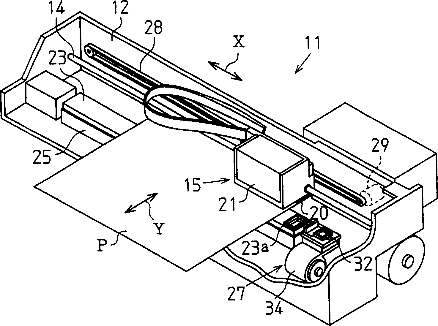
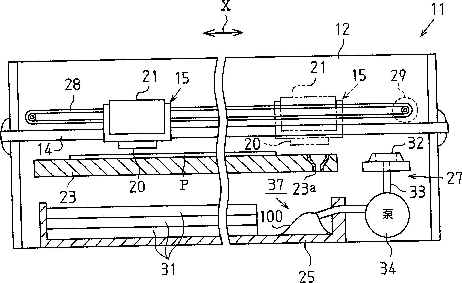
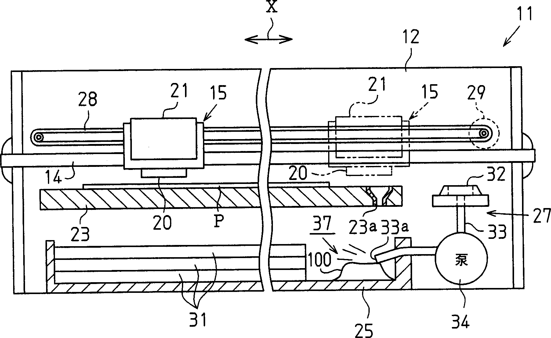
[0028] Such as figure 1 with figure 2 As shown, the printer 11 as the liquid ejecting apparatus of this embodiment is provided with a frame 12, a guide member 14, a carriage 15, a recording head 20 as a liquid ejecting head, an ink cartridge 21, a platen roller 23, a waste liquid tank 25, a head Cleaning mechanism27.

[0029] The frame 12 covers the entirety of the printer 11 . The guide member 14 is provided along the longitudinal direction of the frame 12 . The guide member 14 is inserted through the carriage 15 , whereby the carriage 15 is movably supported relative to the guide member 14 . The carriage 15 is connected to a carriage motor 29 by means of a timing belt 28 , and is driven by the carriage motor 29 to reciprocate along the direction of the guide member 14 , that is, along the main scanning direction X.

[0030] The recording head 20 is mounted on the lower part of the carriage 15, as Figure 4 As shown, a plurality of (in the Figure 4 4) Nozzle 20a in th...


PUM


Abstract

A printer includes a recording head having a nozzle through which ink is ejected onto a paper sheet and a waste tank in which the ink is retained as waste liquid after having been drained from the recording head. A deposit of the waste liquid is formed in the waste tank. The printer has a suction pump used for forcibly drawing and draining the ink from the nozzle. The suction pump functions also as a gas blasting device that blasts gas to the deposit in the waste tank for blowing off the deposit. This suppresses the amount of the ink consumed in maintenance of the printer.

Description

technical field [0001] The present invention relates to a method for cleaning a liquid ejecting device that ejects liquid droplets from a liquid ejecting head, such as an inkjet printing recording device, a display manufacturing device, an electrode forming device, or a biochip manufacturing device, and the liquid ejecting device. Background technique [0002] Conventionally, as a liquid ejecting apparatus that ejects liquid to a target, there is an inkjet printer that ejects ink droplets onto paper to print an image. Such a printer is provided with a recording head having a plurality of nozzles capable of ejecting ink droplets, and the nozzles are always in an ink-filled state. [0003] When the printing is stopped, the ink becomes viscous and solidified due to volatilization of the ink solvent in the nozzle, and dust adheres to the ink in the nozzle. Therefore, such an inkjet printer has a problem of nozzle clogging. Furthermore, since air bubbles are mixed into the ink f...

Claims


Application Information

Patent Timeline
Patent Type & Authority Applications(China)
IPC IPC(8): B41J2/165B41J2/175B41J2/18
Inventor 深泽茂则早川均
Owner SEIKO EPSON CORP
Why Eureka
Try Eureka