
Automatic brake for train running off rails

An automatic braking and train technology, which is applied in the direction of automatic brakes, automatic starting devices, railway car body parts, etc., can solve the problems of not being able to stop in time, and achieve the effect of good effect, low cost and simple structure

Inactive Publication Date: 2006-11-15
CENT SOUTH UNIV
View PDF0 Cites 2 Cited by
  • Summary
  • Abstract
  • Description
  • Claims
  • Application Information

AI Technical Summary

Problems solved by technology

This is because the derailed car is probably not at the head and tail of the train, and at this time the driver or the guard at the rear of the train cannot find the derailed car in time and stop in time.

Method used


Image

  • Automatic brake for train running off rails
  • Automatic brake for train running off rails
  • Automatic brake for train running off rails

Examples


Embodiment Construction

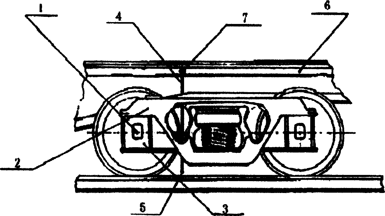
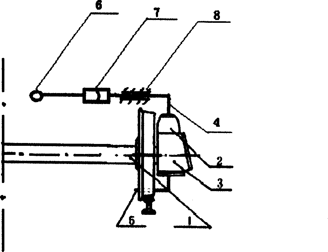
[0018] One of the embodiments of the present invention is to install the trachea sealing end (5) on the side frame (2) next to the wheel set through the air guide tube (4). The sealing end is "L" shaped, and the height from the rail tread is less than the height from the rail tread to the sleeper. When a derailment accident occurs, the sealing end will collide with the rail as the axle box (3) and the side frame (2) on the wheel axle (1) descend. Because the sealing end is made of easily brittle material, it will rupture when it collides with the track, causing the train pipe (6) to deflate and cause the train to stop. After troubleshooting, closing valve (7) just can make train run normally. This scheme is called air duct type derailment brake.

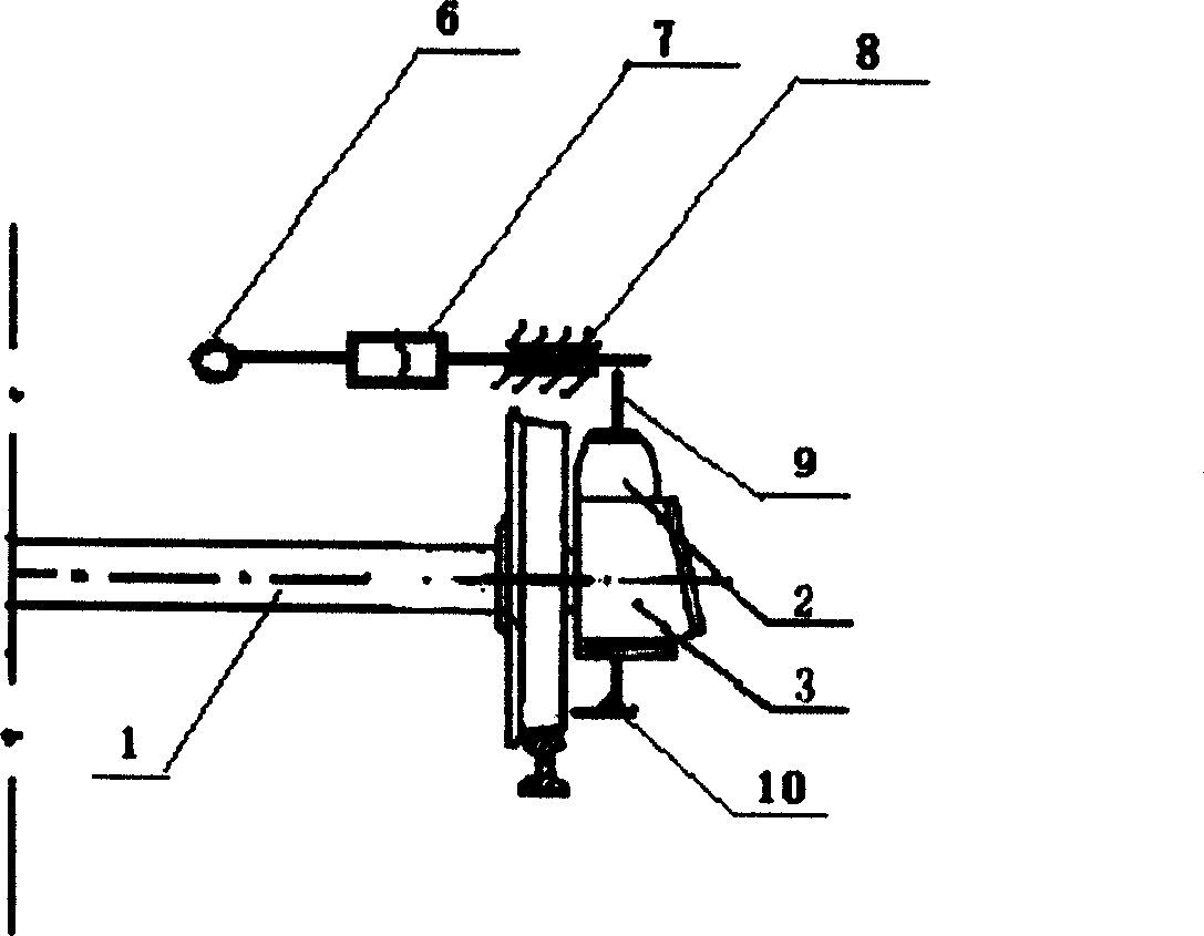
[0019] Two of embodiment of the present invention is that the sealing end of trachea is fixed as image 3 shown. When the wheels of the compartment were derailed, the slide bar (9) descended with the side frame (2) on the wheel a...


PUM


Abstract

An automatic brake for preventing a train from being turned over when the train is derailed features that its main body is a blind air tube made of the fragile material, installed to the steering bogie and connected with the air tube of train. When the train is derailed, the blind air tube is broken by rail and the air is released, resulting in braking.

Description

Technical field: [0001] The invention relates to a device for ensuring the safety of train operation, which can automatically brake the train when it is derailed and prevent the train from overturning. Background technique: [0002] Train overturning accidents happen from time to time. Every time such an accident occurs, it will bring great losses to people's lives and property safety. The train derailment subversion accident is called the "cancer" of railway transportation. [0003] Practice has proved that before the train overturns, the wheelset falls off the rail at first, which is called derailment, and then the wheelset collides violently with the sleeper or other obstacles. When the impact reaches a certain level, an overturning accident will occur. [0004] At present, there is no effective method to stop the train in time at the moment of derailment. This is because the derailed compartment is likely not at the head and tail of the train, and the driver or the gu...

Claims


Application Information

Patent Timeline
Patent Type & Authority Applications(China)
IPC IPC(8): B61H11/02B60T7/22
Inventor 李丰良李敏
Owner CENT SOUTH UNIV
Learn More