
Rotor spinning machine

一种气流纺纱机、纺纱机的技术,应用在薄料处理、运送细丝状材料、运输和包装等方向,能够解决工作站长时间停机、延迟等问题,达到防止不希望地移除筒管、低控制费用的效果

Active Publication Date: 2006-11-15
SAURER GERMANY GMBH & CO KG
View PDF1 Cites 7 Cited by
  • Summary
  • Abstract
  • Description
  • Claims
  • Application Information

AI Technical Summary

Problems solved by technology

The resulting delays can lead to undesirably long downtime of workstations

Method used


Image

  • Rotor spinning machine
  • Rotor spinning machine

Examples


Embodiment Construction

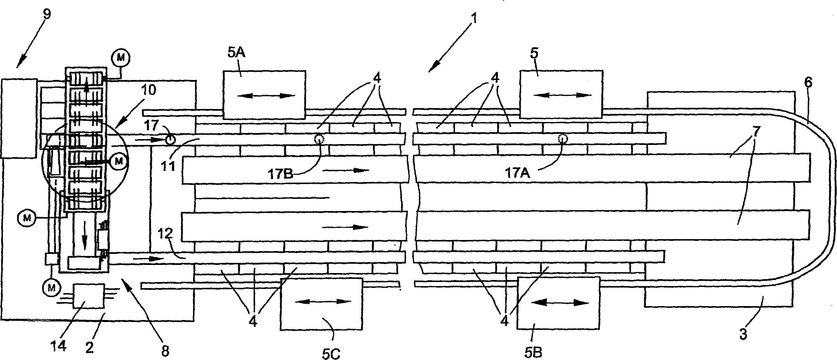
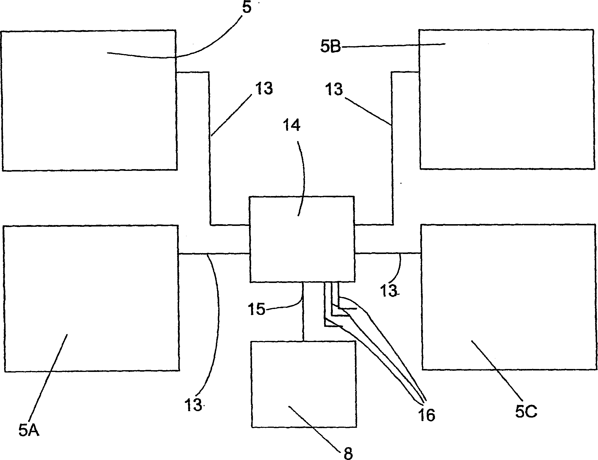
[0015] figure 1 The air spinning machine 1 shown has a plurality of work stations 4 between the end positions 2 and 3, which are arranged on both longitudinal sides of the spinning machine. The workstations 4 , which in each case include the weaving and winding mechanisms, are maintained by four maintenance units 5 , 5A, 5B, 5C. The maintenance units 5 , 5A, 5B, 5C are movable along the machine side on the guide rail structure 6 . One of the maintenance units 5, 5A, 5B, 5C works automatically if a yarn break occurs at one of the workstations 4 or a bobbin needs to be replaced. The air spinning machine 1 further comprises a cross-winding bobbin conveying device 7 and a bobbin feeding device 8 arranged between the workstations 4, the cross-winding bobbin conveying device 7 is used for conveying the completed cross-winding bobbins. The bobbin supply device 8 (in this example) comprises a central bobbin magazine 9 arranged at the end of the machine, a bobbin distribution device ...


PUM


Abstract

The invention relates to a rotor spinning machine comprising a plurality of working stations and a bobbin supplying device extending along the machine. At least two service units supplying the working stations with bobbins are supplied with bobbins by the supply device. A control device (14) for controlling the service units (5, SA, SB, SC) is embodied in such a way that it prevents a subsequent request for bobbins from the second service unit (5A) during a request for bobbins from the first service unit (5) positioned downstream in relation to the transport direction of the supply device, until the previous bobbin request has been fulfilled. In this way, unnecessary downtime of the working stations and unnecessary waiting time for the service units (5, 5A, 5B, SC) is avoided.

Description

technical field [0001] The invention relates to an air spinning machine according to the preamble of claim 1 . Background technique [0002] A maintenance unit is used on the air spinning machine and is movable on guide rails on the longitudinal sides of the air spinning machine. The function of the maintenance device is to start spinning after a yarn break and to supply the bobbins to the spinning station of the rotor spinning machine. In order to keep the downtime of the spinning station as short as possible in the event of a yarn break or bobbin change, several maintenance units are used on the rotor spinning machine, for example two on each longitudinal side of the spinning machine. [0003] DE 199 05 856 A1 describes an air spinning machine with a plurality of workstations between its end frames, which are arranged on both longitudinal sides of the spinning machine. Each of these workstations has a spinning mechanism and a downstream winding mechanism, and is supplied...

Claims


Application Information

Patent Timeline
Patent Type & Authority Applications(China)
IPC IPC(8): B65H67/06
CPCB65H67/068B65H2701/31
Inventor 沃尔夫冈·德尔纳拉尔夫·西韦特洛伦茨·克赖茨恩
Owner SAURER GERMANY GMBH & CO KG
Learn More