
Real-time monitoring system for preventing electricity theft for power network

A real-time monitoring system and anti-power stealing technology, applied in signal transmission systems, measuring devices, measuring electrical variables, etc., can solve the problem of inability to complete the system comprehensive line loss analysis alone, difficult to grasp the operating status of the distribution network in real time, and insufficient census. And other issues

Inactive Publication Date: 2006-11-22
湖南泰通能源管理股份有限公司
View PDF0 Cites 35 Cited by
  • Summary
  • Abstract
  • Description
  • Claims
  • Application Information

AI Technical Summary

Problems solved by technology

[0003] 1. It mainly protects the 0.4kV user-side metering device, but there are thousands of methods of stealing electricity, and it is impossible to effectively prevent the electricity theft without using the metering device
Therefore, any technical preventive measures aimed at a single metering device cannot effectively prevent the occurrence of electricity theft;
[0004] 2. Traditional anti-stealing inspections mainly rely on manual business censuses. The timeliness is poor and the census is not in place. It is difficult to grasp the operation status of the distribution network in real time and accurately provide the time, place and related data of the electricity theft. It is difficult to verify
[0005] 3. The existing distribution network line loss analysis system can only give the line loss of the entire feeder, but cannot give the line loss of any branch or node in the feeder. Therefore, the line loss analysis system based on the power automation system can Unable to complete the comprehensive line loss analysis of the entire system alone

Method used


Image

  • Real-time monitoring system for preventing electricity theft for power network
  • Real-time monitoring system for preventing electricity theft for power network
  • Real-time monitoring system for preventing electricity theft for power network

Examples


Embodiment 1

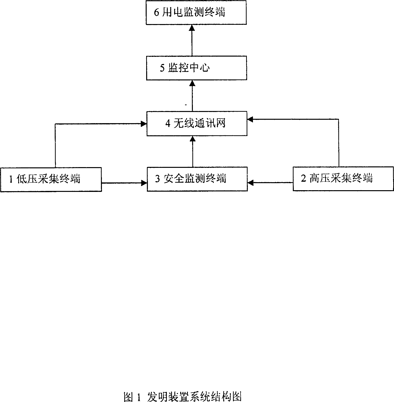
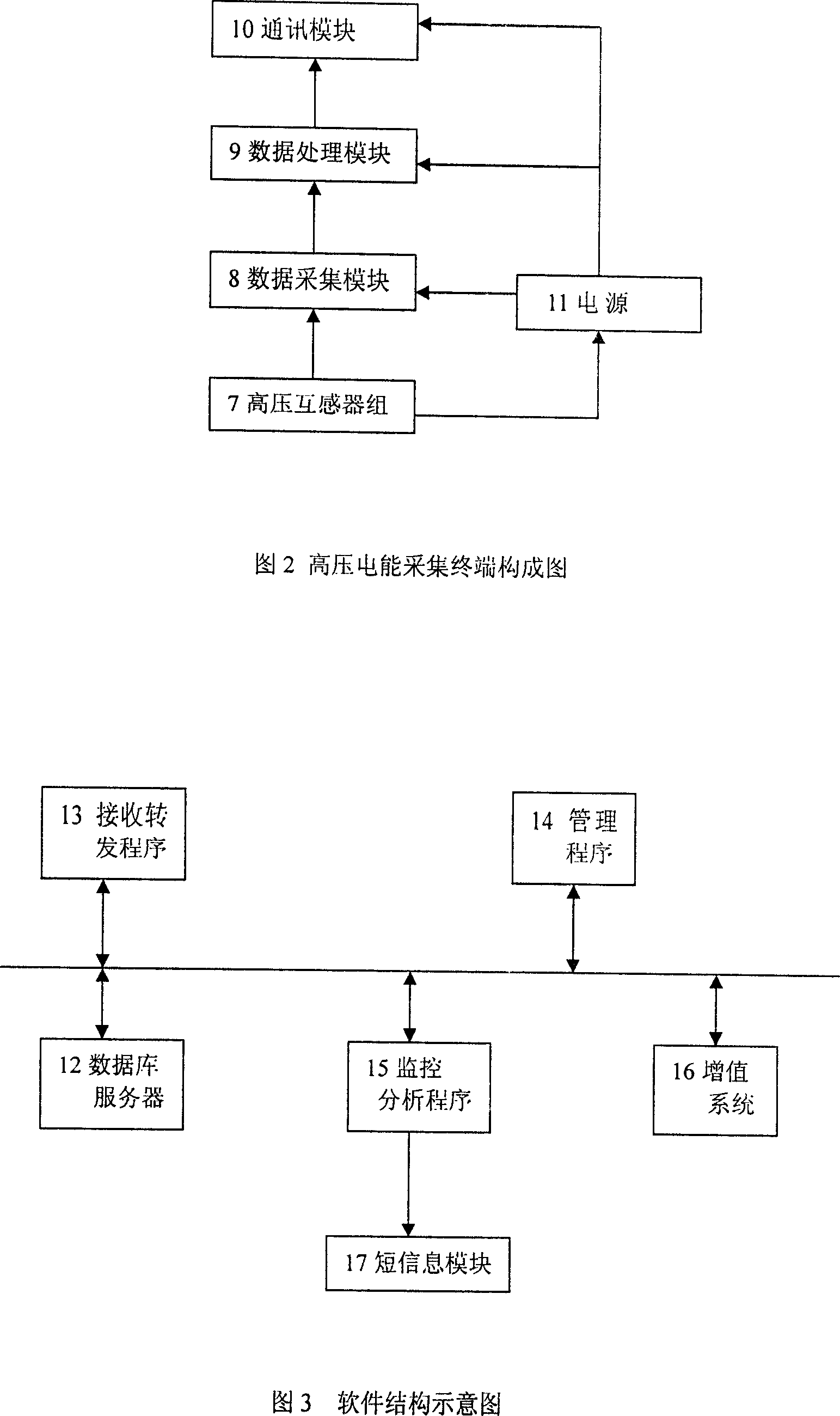
[0016] Embodiment 1: As shown in Figure 1, the device of the present invention consists of a high-voltage power collection terminal 2, a low-voltage power collection terminal 1, a wireless digital public communication network 4, a safety monitoring terminal 3, a monitoring center 5 and a mobile power supervision terminal 6. The high-voltage electric energy collection terminal 3 is installed in the feeder line, node, and the high-voltage side of the transformer to independently collect the load parameters of the 10kV (35kV) side of the distribution network; The power collection terminal 1 adopts a distribution transformer collection terminal, and the collection box is installed on the pole of the substation. The operating parameters of the transformer are collected through the combination of transformers, and the parameters of multi-channel metering meters can be collected at the same time. The parameters collected by each collection terminal are transmitted to the monitoring ce...

Embodiment 2

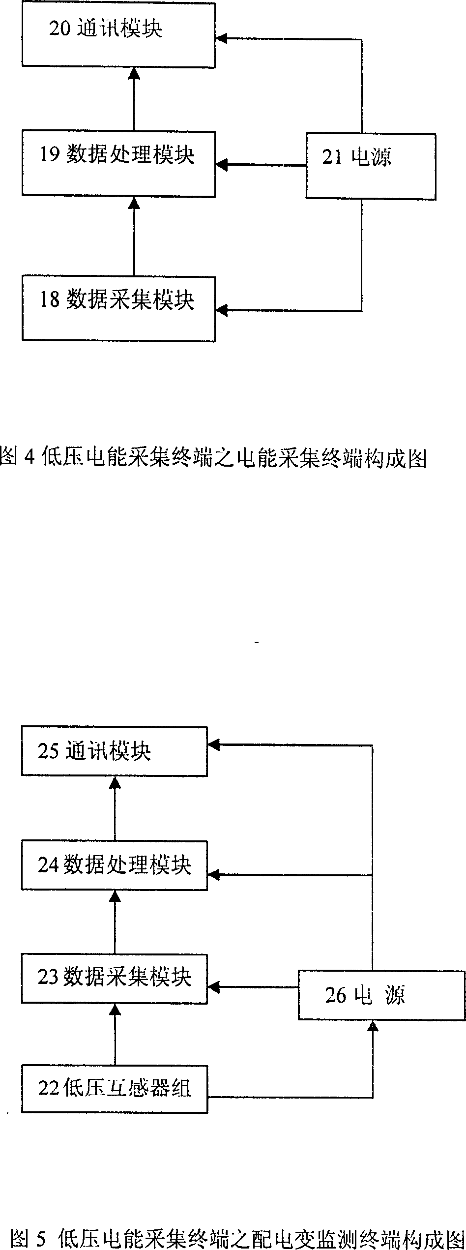
[0017] Embodiment 2: On the basis of Embodiment 1, if the electric energy metering device at the low-voltage side monitoring point has a data interface, the low-voltage electric energy collection terminal 1 adopts the electric energy collection terminal and is installed on the secondary outlet side of the metering transformer, through RS485 or The pulse interface collects the data of the metering device.


PUM


Abstract

The disclosed real-time method to prevent electric larceny comprises: monitoring the transformer substation pass, 10KV distribution lines, special user and public power parameter by a high-voltage electric energy collection terminal; monitoring original parameters by a low-voltage electric energy collection terminal; using a wireless digital communication network to send data to the monitor center to store in database for classification and analysis, then auto drawing load curve and charge curve for different monitor point. This invention has well monitor effect and can alarm by SMS.

Description

Technical field: [0001] The invention relates to a method and device for preventing electricity theft, in particular to a method and a device for managing electricity theft from the power supply side and analyzing and checking electricity theft from the system side. Background technique: [0002] The existing grid anti-theft methods mainly have the following problems: [0003] 1. It mainly protects the 0.4kV user-side metering device, but there are thousands of ways to steal electricity, and it cannot be effectively prevented without using the metering device to steal electricity. Therefore, any technical preventive measures aimed at a single metering device cannot effectively prevent the occurrence of electricity theft; [0004] 2. The traditional anti-stealing inspection mainly relies on manual business census, which has poor timeliness and insufficient census. It is difficult to grasp the operation status of the distribution network in real time, and it is difficult to a...

Claims


Application Information

Patent Timeline
IPC IPC(8): G01R11/24G08C17/02
Inventor 王苇莫立宇颜运昌何林毅伍忠刘铮陈维红舒畅
Owner 湖南泰通能源管理股份有限公司
Learn More