
Liquid crystal panel and liquid crystal display apparatus

A liquid crystal panel, cellulose-based technology, applied in the field of liquid crystal panels and liquid crystal display devices, can solve the problems of reduced oblique contrast and increased color shift, and achieve the effects of small color shift, excellent oblique contrast, and excellent viewing angle compensation

Inactive Publication Date: 2006-11-22
NITTO DENKO CORP
View PDF8 Cites 3 Cited by
  • Summary
  • Abstract
  • Description
  • Claims
  • Application Information

AI Technical Summary

Problems solved by technology

However, when conventional retardation plates are used in conventional configurations in liquid crystal display devices, oblique contrast often decreases and color shift often increases

Method used


Image

  • Liquid crystal panel and liquid crystal display apparatus
  • Liquid crystal panel and liquid crystal display apparatus
  • Liquid crystal panel and liquid crystal display apparatus

Examples


preparation example Construction

[0048] The production method of the polarizer includes subjecting a polyvinyl alcohol-based resin film to a production process including a dyeing step, a crosslinking step, a stretching step, a washing step, and a drying step. In each step except the drying step, each treatment is carried out by immersing a polyvinyl alcohol-based resin in a bath containing a solution to be used in each step. The order and number of dyeing steps, crosslinking steps, stretching steps, washing steps, and drying steps, and implementation and omission of treatments can be appropriately set according to purposes, materials used, conditions, and the like. For example, several processes may be performed simultaneously in one step, or certain processes may be omitted. Specifically, stretching treatment may be performed after, before, or during dyeing treatment and crosslinking treatment, for example. In addition, for example, dyeing treatment is preferably performed before or after stretching treatme...

Embodiment 1

[0239] [Reference Example 1: Production of Cellulosic Film (1)]

[0240] Cyclopentanone was coated on polyethylene terephthalate, and then the whole was attached to a triacetyl cellulose film ("UZ-TAC", trade name, purchased from Fuji Film Industries, Ltd.) with a thickness of 40 μm. Co., Ltd., Re(590)=3nm, Rth(590)=40nm). The resultant was dried at 100° C. for 5 minutes, and after drying, the polyethylene terephthalate film was peeled off. Re(590) of the obtained cellulose-based film (1) was 0.2 nm and Rth(590) was 5.4 nm.

Embodiment 2

[0241] [Reference Example 2: Production of Cellulosic Film (2)]

[0242] The norbornene-based resin was dissolved in cyclopentanone to prepare a solution having a solid content of 20% by weight. This solution was applied to a triacetyl cellulose film ("UZ-TAC", trade name, purchased from Fuji Film Industry Co., Ltd., Re(590)=3 nm, Rth(590)=40 nm) with a thickness of 40 μm) On, the coating thickness is 150 μm. The resultant was dried at 140°C for 3 minutes, and after drying, the norbornene-based resin formed on the surface of the triacetylcellulose film was peeled off. Re(590) of the obtained cellulose-based film (2) was 1.1 nm and Rth(590) was 3.4 nm.


PUM

PropertyMeasurementUnit
thicknessaaaaaaaaaa
thicknessaaaaaaaaaa
thicknessaaaaaaaaaa

Abstract

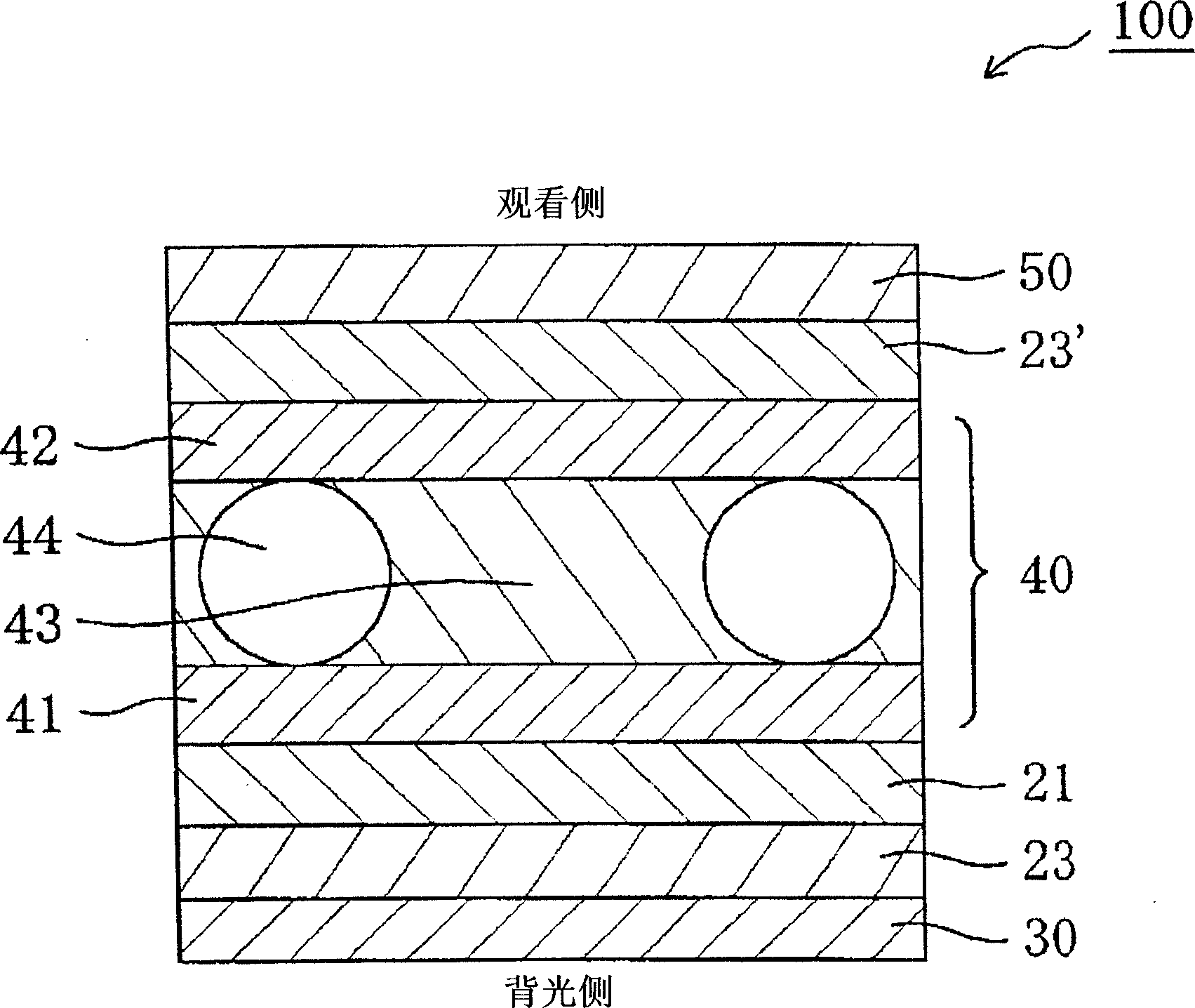
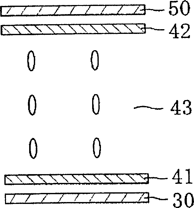
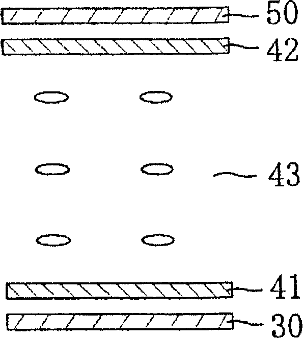
The present invention provides a liquid crystal panel and a liquid crystal display device each giving excellent viewing angle compensation and having excellent oblique contrast and small color shift. The liquid crystal panel of the present invention comprises in a specific order from the backlight side to the viewing side: a first polarizer, a first cellulose-based film, an optical compensation layer having an Nz coefficient represented by the relational formula (1) 2≤Nz≤20, A liquid crystal cell, a second cellulose-based film, and a second polarizer, wherein the retardation (Rth) in the thickness direction of the first cellulose-based film is expressed by relational formula (2), which is less than or equal to 10 nm; and the second cellulose The phase difference (Rth) in the thickness direction of the film-like film is expressed by the relational formula (2), which is less than or equal to 10nm: Nz=(nx-nz) / (nx-ny)...(1) Rth=(nx-nz)× d...(2).

Description

technical field [0001] The present invention relates to a liquid crystal panel and a liquid crystal display device. More specifically, the present invention relates to a liquid crystal panel and a liquid crystal display device each giving excellent viewing angle compensation, and having excellent oblique contrast and small color shift. Background technique [0002] Figure 7A shows a schematic cross-sectional view of a typical conventional liquid crystal display device, Figure 7B A schematic cross-sectional view of a liquid crystal cell used in the liquid crystal display device is shown. The liquid crystal display device 900 is configured with a liquid crystal cell 910 , retardation plates 920 and 920 ′ disposed outside the liquid crystal cell 910 , and polarizers 930 and 930 ′ disposed outside the retardation plates 920 and 920 ′, respectively. Generally, the polarizing plates 930 and 930' are configured such that their respective absorption axes are perpendicular to eac...

Claims


Application Information

Patent Timeline
Patent Type & Authority Applications(China)
IPC IPC(8): G02F1/1335G02F1/133
CPCG02F1/133634G02F1/1393G02F1/1335G02F1/13363
Inventor 木谷良幸吉见裕之村上奈穗武田健太郎
Owner NITTO DENKO CORP
Learn More