Improved CD rack

A technology for optical discs and tubular components, which is applied in the field of furniture, can solve the problems of heavy disc racks, unsightly appearance, low structural strength, etc., and achieves the effects of beautiful appearance, improved flexural section modulus, and reduced material consumption.

Inactive Publication Date: 2006-11-22
上海温兴生物工程有限公司
View PDF0 Cites 1 Cited by
  • Summary
  • Abstract
  • Description
  • Claims
  • Application Information

AI Technical Summary

Problems solved by technology

[0003] The object of the present invention is to provide an improved disc rack, which solves the problems of heavy weight, corrosion resistance, high cost, low structural strength and unattractive appearance in the prior art. technical problem

Method used


Image

  • Improved CD rack
  • Improved CD rack
  • Improved CD rack

Examples


Embodiment Construction

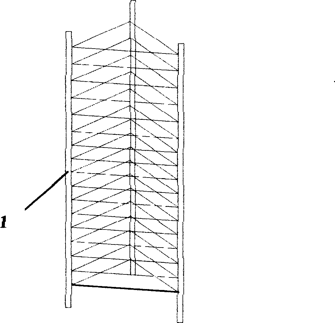
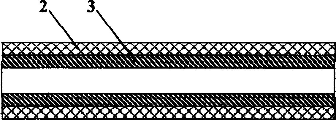
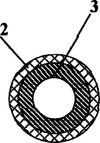
[0012] Such as figure 1 , figure 2 and image 3 As shown, an improved disc rack of the present invention is composed of at least three longitudinal tubular members 1, and transverse connectors are arranged between the tubular members 1, wherein any one of the tubular members 1 is respectively It is composed of stainless steel pipe body 2, and any one of the stainless steel pipe bodies 2 is provided with a reinforced fiber plastic pipe body 3, and the diameter of the reinforced fiber plastic pipe body 3 matches the diameter of the stainless steel pipe body 2 , the stainless steel pipe body 2 and the reinforced fiber plastic pipe body 3 are fixedly connected.

[0013] Further, the radial section of the tubular member 1 is circular, or rectangular, or square, or has a special-shaped section.

[0014] Further, the tubular member 1 is arranged parallel or non-parallel in the longitudinal direction.

[0015] Furthermore, the tubular member 1 is arranged in a straight line, or a...


PUM


Abstract

The improved CD frame comprises at three vertical stainless-steel tubular elements with horizontal connection members connected. Wherein, it arranges reinforced fiber plastic tube in every stainless steel tube connected together. This invention has simple structure, light weight, and pretty view fit to corrosion prevention.

Description

technical field [0001] The invention relates to furniture, in particular to a shelf for placing optical discs, in particular to an improved optical disc rack. Background technique [0002] At present, furniture such as CD racks can be seen everywhere in people's daily life, and are widely used in households, enterprises, hotels, and some public places. However, the main components used in the materials of CD racks are various types of stainless steel, wood, etc. , or mainly made of plastic materials, stainless steel is expensive and heavy, although the cost of wood and plastic is not high, they are not corrosion-resistant, and the cost of stainless steel materials is relatively high. Less, thus its structural strength of the disc rack made can not be guaranteed, in addition, the disc rack made of wood, plastics is not attractive in appearance again. Contents of the invention [0003] The object of the present invention is to provide an improved disc rack, which solves the...

Claims


Application Information

Patent Timeline
IPC IPC(8): G11B23/03G11B33/04
Inventor 陈宏强王耀庭
Owner 上海温兴生物工程有限公司
Why Eureka
Try Eureka