Health data collection apparatus
A technology for collecting system and health data, applied in data processing applications, medical science, instruments, etc., to achieve the effect of increasing data volume, smooth communication, and benefiting remote health care
- Summary
- Abstract
- Description
- Claims
- Application Information
AI Technical Summary
Problems solved by technology
Method used
Image
Examples
no. 1 approach
[0075] The following describes the health data collection system according to the present invention according to the implementation manner.
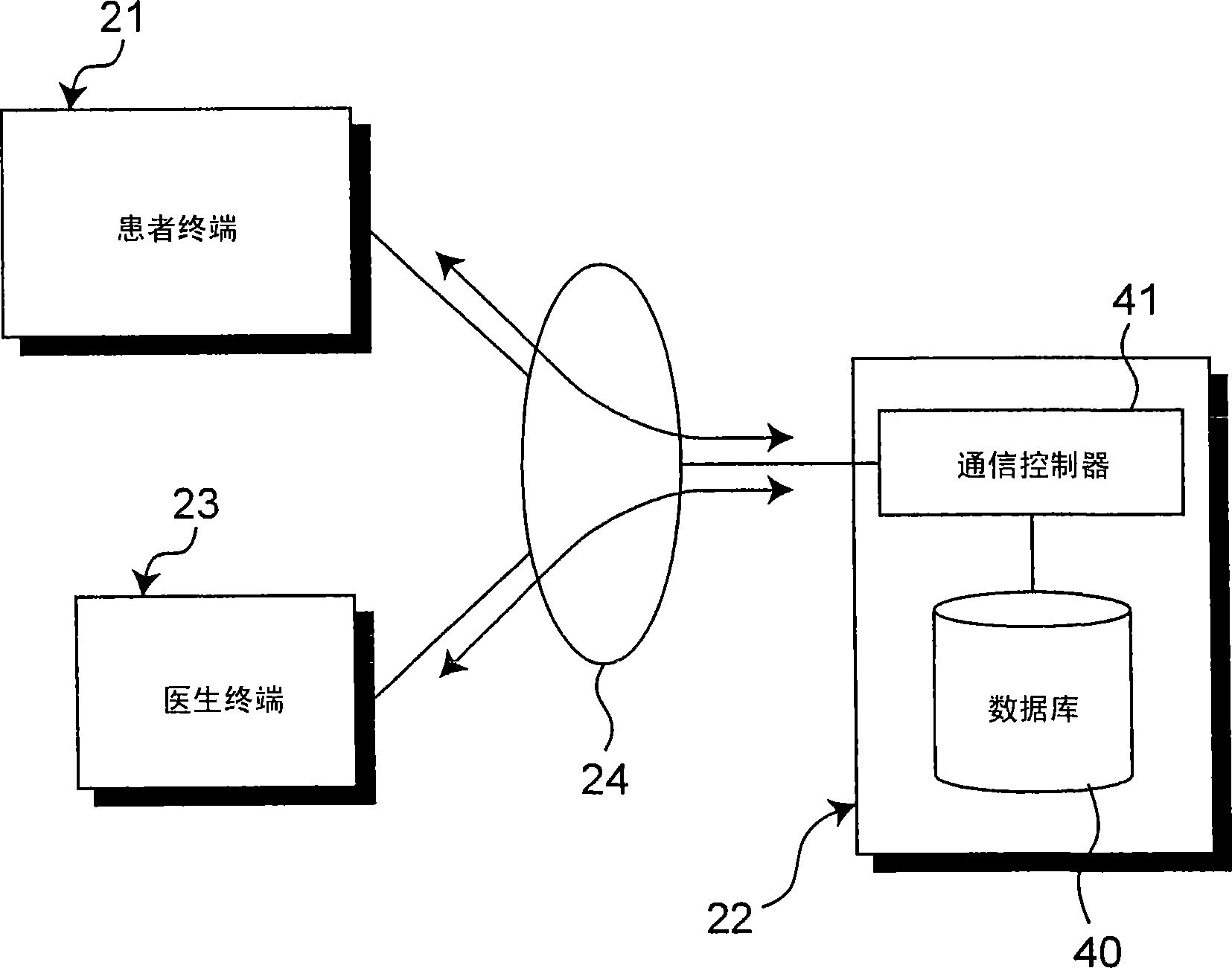
[0076] figure 1 A block diagram of the health data collection system according to the first embodiment of the present invention is shown. The health data acquisition system generally includes: a patient terminal 21, which is arranged on the patient side as the person to be measured; a central server 22, as an accumulation unit, for accumulating data collected from the patient terminal 21; and a health care provider terminal or a doctor terminal 23, which is used by a healthcare provider, such as a doctor, to consult data stored in the central server 22. The patient terminal 21 , the center server 22 and the doctor terminal 23 are connected to each other via a communication network 24 .
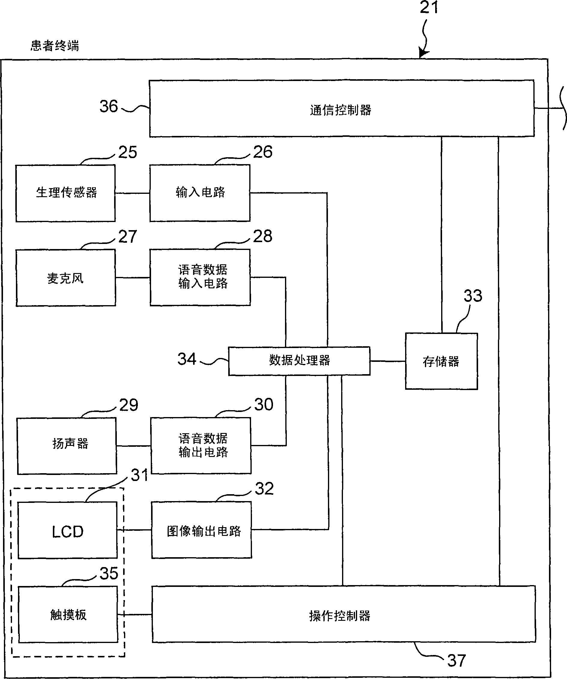
[0077] further reference figure 2 , the patient terminal 21 includes: a physiological sensor (measuring unit) 25, such as a thermometer, a sphygmom...
no. 2 approach
[0101] The health data acquisition system of the second embodiment of the present invention differs from the first embodiment in that image data can be added to physiological data in addition to voice data.
[0102] refer to Figure 8 , the patient terminal 21 of the second embodiment includes a camera 38 for image capture and an image input circuit 39 for the camera 38 . The data processor 34 has a function of associating image data from the camera 38 with voice data from the microphone 27 and stores the data in the memory 33 . In addition, the data processor 34 has a function of extracting physiological data stored in the memory 33 and associated image data and voice data, and causing the liquid crystal display 31 and the speaker 29 to output it.
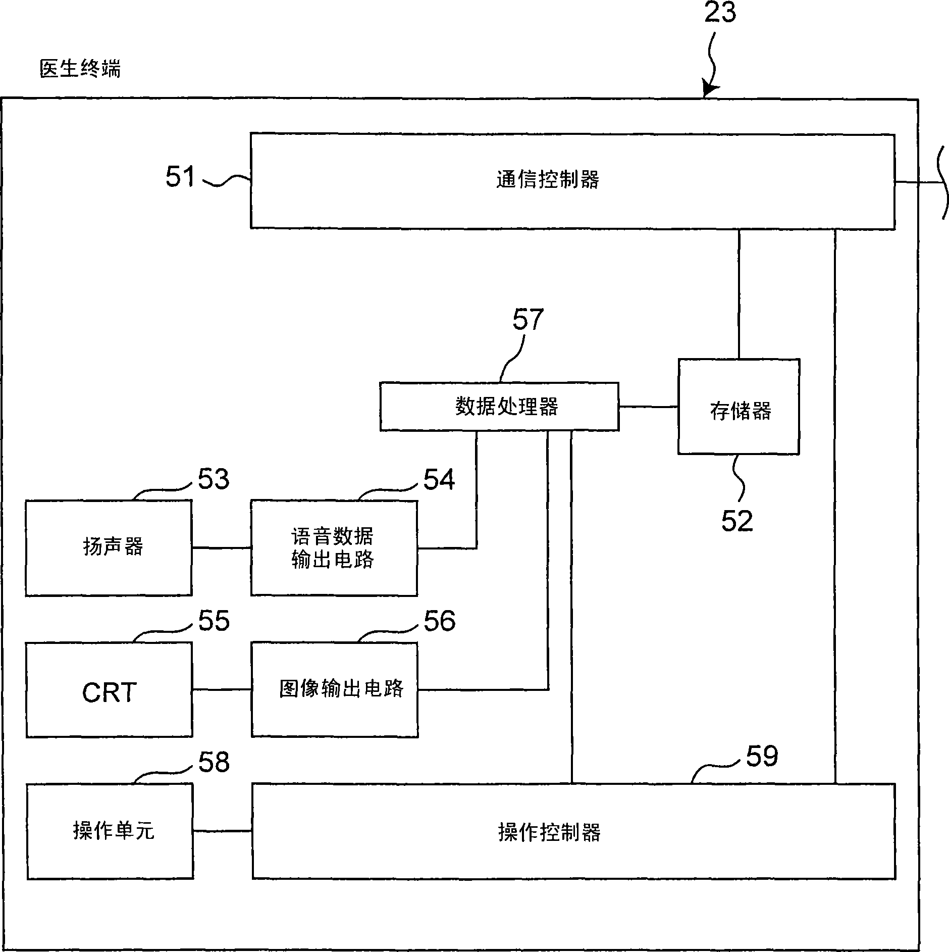
[0103] The data processor 57 (see 3) of the doctor terminal 23 of the second embodiment extracts the physiological data, voice data, and image data stored in the memory 52, correlates these data with each other, and makes the spe...
no. 3 approach
[0110] Figure 12 The appearance of the patient terminal 221 of the health data collection system according to the third embodiment of the present invention is shown. The difference between this embodiment and the first embodiment is that although the terminal includes a liquid crystal display 240, the terminal does not include a touch panel ( figure 2 reference symbol 35). In other words, the liquid crystal display 240 only has a display function.
[0111] The patient terminal 221 of the present embodiment includes, as an operation unit instead of a touch panel, a down / up button 244 , an "OK" button 243 , a cancel button 242 , and a number button 241 , all of which are buttons. Similar to the patient terminal 21 of the first embodiment, the patient terminal 221 includes a microphone 216 for voice input.
[0112] Figure 13 is an example of a screen of the liquid crystal display 240 . with the first embodiment Figure 4 Similarly, this example is the screen displayed im...
PUM
 Abstract
Description
Claims
Application Information
 - R&D
- Intellectual Property
- Life Sciences
- Materials
- Tech Scout
- Unparalleled Data Quality
- Higher Quality Content
- 60% Fewer Hallucinations
Browse by: Latest US Patents, China's latest patents, Technical Efficacy Thesaurus, Application Domain, Technology Topic, Popular Technical Reports.
© 2025 PatSnap. All rights reserved.Legal|Privacy policy|Modern Slavery Act Transparency Statement|Sitemap|About US| Contact US: help@patsnap.com


