Hybrid sphere-waveguide resonators

一种谐振器、微型谐振器的技术,应用在光波导光导、光波导的耦合、仪器等方向,能够解决未解决微球体和波导管耦合等问题

Inactive Publication Date: 2006-11-22
3M INNOVATIVE PROPERTIES CO
View PDF0 Cites 15 Cited by
  • Summary
  • Abstract
  • Description
  • Claims
  • Application Information

AI Technical Summary

Problems solved by technology

This approach maintains the high Q of the glass spheres, but does not solve the problem of how to precisely control the coupling between the microspheres and the waveguide

Method used


Image

  • Hybrid sphere-waveguide resonators
  • Hybrid sphere-waveguide resonators
  • Hybrid sphere-waveguide resonators

Examples


Embodiment Construction

[0026] The present invention can be applied to passive and active optical devices, such as sensors, filters, amplifiers, and / or micro lasers using micro resonators such as micro spheres and micro planar ring resonators. The present invention can be believed to be particularly useful for manufacturing such devices. Since the relative position of the microresonator and the waveguide can be controlled, the Q value of the microresonator can be high, and the light beam can be easily transmitted and received.

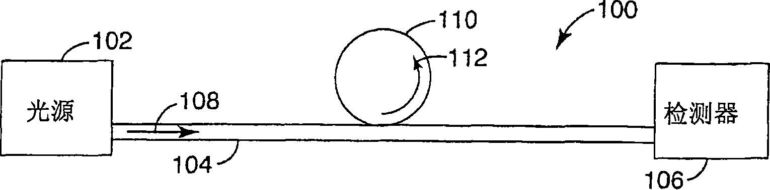
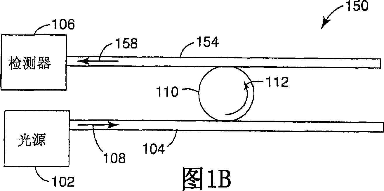
[0027] in Figure 1A The microsphere waveguide system 100 using microresonators is schematically shown in FIG. The light source 102 guides the light along the waveguide 104 to the detector unit 106. The micro resonator 110 is optically coupled to the waveguide 104. Light 108 is emitted from the light source 102 into the waveguide 104 and propagates toward the detector unit 106. The micro resonator 110 evanescently couples some of the light 108 out of the waveguide 104, and the co...


PUM

PropertyMeasurementUnit
diameteraaaaaaaaaa

Abstract

Microresonators, such as a microsphere resonators (312) and planar microresonators (612), are optically coupled to waveguides (304, 604) for input and output of light. It is important that the relative positions of the microresonator and the waveguide are maintained stable, while still maintaining high cavity Q and ease of launching and extracting the optical beams. Structures (308, 608) are provided on a substrate that are useful for maintaining the position of the microresonator relative to the waveguide. The structures provide for vertical or horizontal coupling between the waveguide and the microresonator.

Description

Invention field [0001] The present invention relates generally to optical devices, and more specifically to passive and active optical devices based on miniature resonators, such as optical sensors, optical filters, and miniature lasers. Background technique [0002] In photoelectric and sensing applications including biosensing, dielectric microresonators have attracted more and more attention. The common configuration of micro-resonators includes glass microspheres, the diameter of which is generally 20μm to several millimeters, and the microspheres are placed near the optical waveguide, for example, after heating and sharpening or etching into a total thickness of 1-5μm Optical fiber. [0003] Here, the tapered deformation of the fiber creates a considerable light field intensity outside the fiber, so light can couple into the microsphere and excite its natural mode (eigenmode), which is usually called whispering gallery mode (WGM) . When the micro-resonator is made of low-los...

Claims


Application Information

Patent Timeline
Patent Type & Authority Applications(China)
IPC IPC(8): G02B6/293G01N21/55G01N21/64G01N21/77G02B6/10G02B6/12G02B6/26G02B6/28G02B6/34G02B6/36
CPCG01N21/552G01N21/645G01N21/648G01N21/7746G01N2021/6484G02B6/12007G02B6/26G02B6/29341G02B6/3652G02B6/3692G02B6/4246G02F2203/15
Inventor 范旭东约翰·E·波特特里·L·史密斯罗伯特·W·威尔逊
Owner 3M INNOVATIVE PROPERTIES CO
Why Eureka
Try Eureka