Planar light source device and display device using the same
A light source device, planar technology, applied in the direction of point light source, light source, electric light source, etc., can solve the problems of increased assembly steps, higher production costs, and higher costs, and achieve the effect of stable chromaticity
- Summary
- Abstract
- Description
- Claims
- Application Information
AI Technical Summary
Problems solved by technology
Method used
Image
Examples
Embodiment approach 1
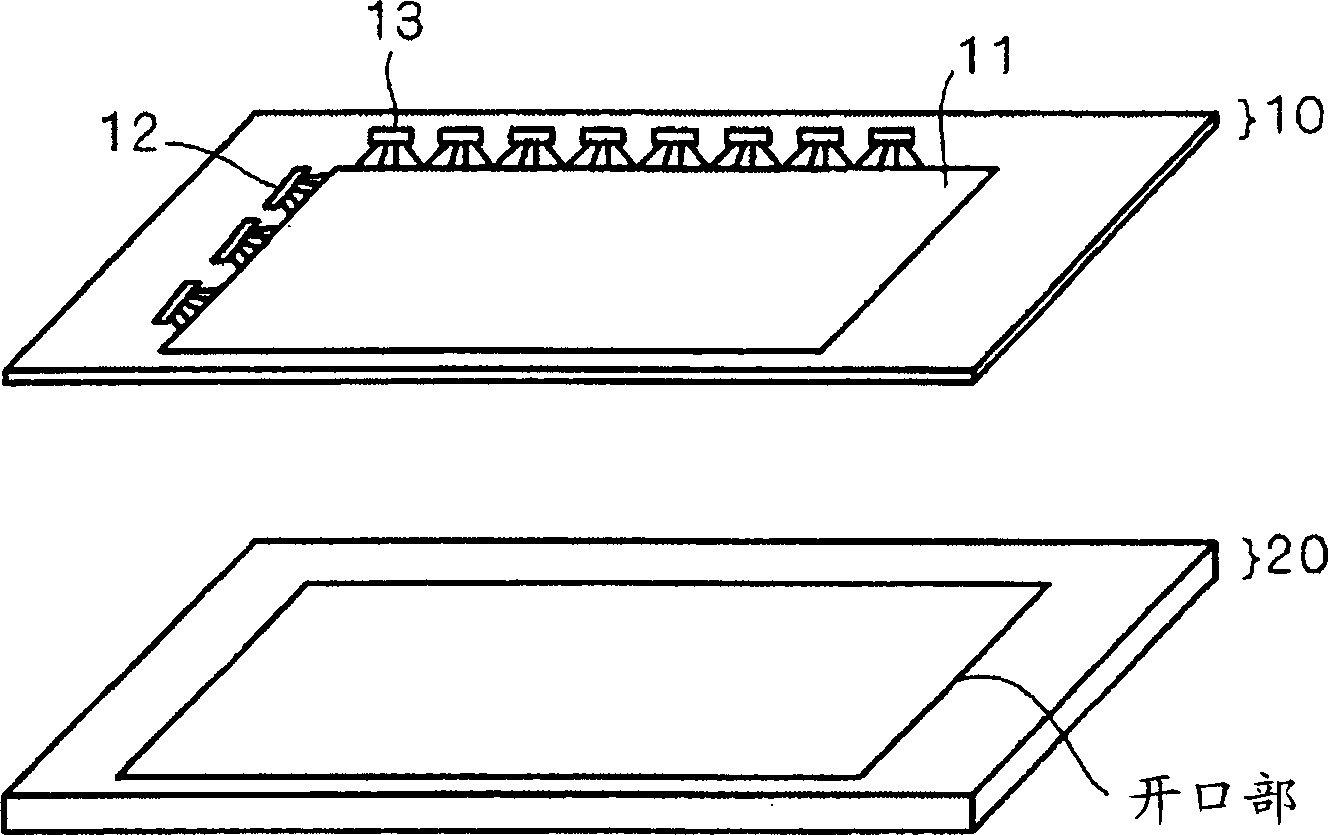
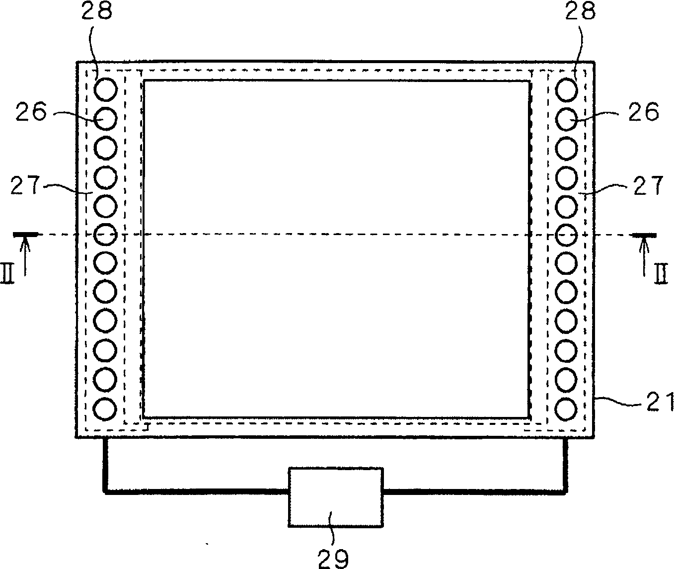
[0023] In this embodiment mode, a mode in which a planar light source device is used as a backlight of a liquid crystal display device will be described. However, the planar light source device of the present invention is not limited to the above-described forms. first, figure 1 It is an exploded perspective view showing the structure of the liquid crystal display device of this embodiment. figure 1 The illustrated liquid crystal display device is provided with: a liquid crystal display panel 10 for writing and displaying a desired image in pixels; and a backlight 20 for irradiating light from the back of the liquid crystal display panel 10 . The liquid crystal display panel 10 holds liquid crystals between opposing substrates 11 , and in order to drive the liquid crystals, TFTs (Thin Film Transistor: Thin Film Transistors) (not shown) are formed in a matrix on one substrate 11 . Furthermore, pixels (not shown) connected to TFTs are also formed in a matrix. Furthermore, the...
Embodiment approach 2
[0062] Figure 9 It is a figure which shows the structure of the light source unit 28 of the planar light source device of this embodiment. Figure 10 Yes Figure 9 A wiring diagram of the light source unit 28 is shown. In the light source unit 28 of this embodiment, a row of RGB light emitting diodes 26 is mounted on a rectangular circuit substrate 27 , and furthermore, light emitting diodes 31 having longer wavelengths than the R light emitting diodes 26 are mounted. exist Figure 9 Among them, the light-emitting diode 31 is arranged on the right side of the third light-emitting diode 26 on the left side and the left side of the third light-emitting diode 26 on the right side. Moreover, in this embodiment, the infrared light-emitting diode 31 of IR (infrared) whose main wavelength is infrared wavelength (780 nm or more) is used. In addition, when expressing Figure 9 IR is indicated in the circle of the LED 31 .
[0063] One IR light-emitting diode 31 may be attached t...
PUM
| Property | Measurement | Unit |
|---|---|---|
| reflectivity | aaaaa | aaaaa |
| wavelength | aaaaa | aaaaa |
Abstract
Description
Claims
Application Information
 - R&D
- Intellectual Property
- Life Sciences
- Materials
- Tech Scout
- Unparalleled Data Quality
- Higher Quality Content
- 60% Fewer Hallucinations
Browse by: Latest US Patents, China's latest patents, Technical Efficacy Thesaurus, Application Domain, Technology Topic, Popular Technical Reports.
© 2025 PatSnap. All rights reserved.Legal|Privacy policy|Modern Slavery Act Transparency Statement|Sitemap|About US| Contact US: help@patsnap.com


