Wind-mill generator

A generator and magnet technology, applied in wind power generation, electrical components, electromechanical devices, etc., can solve the problems of reduced wind power generation efficiency, increased generator starting resistance torque, and increased cut-in wind speed, so as to improve wind power generation efficiency and reduce cost effect

Inactive Publication Date: 2006-11-29
FLY RENEWABLE ENERGY TECH
View PDF0 Cites 5 Cited by
  • Summary
  • Abstract
  • Description
  • Claims
  • Application Information

AI Technical Summary

Problems solved by technology

However, a large rated wind speed corresponds to a large rated power of the generator, which increases the starting resistance torque of the gen

Method used


Image

  • Wind-mill generator
  • Wind-mill generator
  • Wind-mill generator

Examples


Embodiment Construction

[0035] specific implementation plan

[0036] The present invention will be further described below in conjunction with accompanying drawing and embodiment:

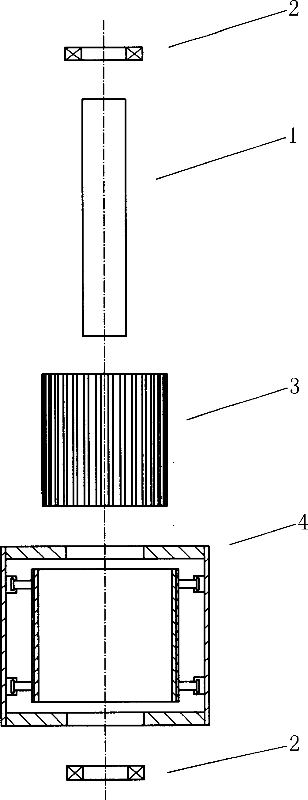
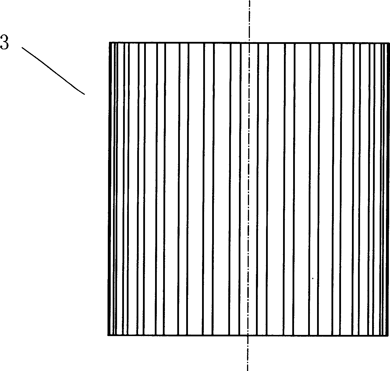
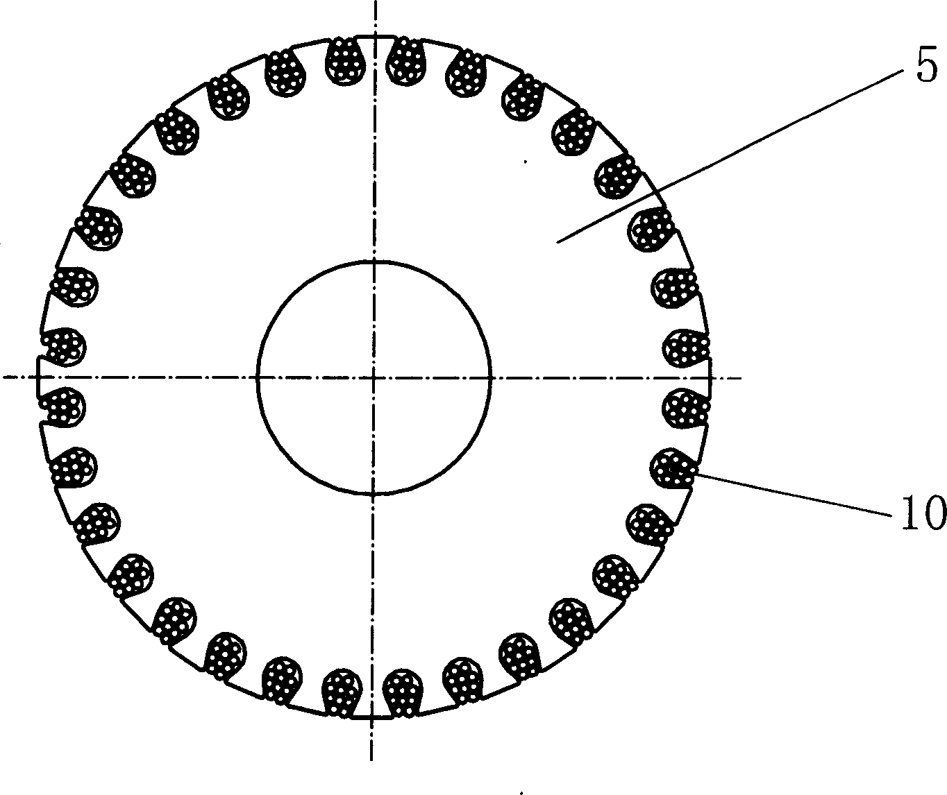
[0037] Figure 1 to Figure 9 , Figure 14 with Figure 15 It is the main assembly and its structure schematic diagram of the present invention. figure 1 It is shown that the generator of the present invention is composed of a main shaft 1, a bearing 2, an inner body 3 and an outer body 4, figure 2 with image 3 It is shown that the inner body 3 is composed of an iron core 5 and an armature winding 10, Figure 4 with Figure 5 is a structural schematic diagram of the exosome 4, Figure 14 with Figure 15 is another schematic diagram of the exosome 4; Image 6 , Figure 7 with Figure 8 It can be seen that the exciter is composed of a permanent magnet 11 and a magnet 9 formed with a yoke 12. Figure 9 It can be seen that the exciter can also be composed of a magnet 9 composed of an excitation winding 13 and a y...


PUM


Abstract

This invention discloses a wind-mill generator characterizing that relative displacement occurs between the rotor and the stator by a driver, therefore, the magnetic induction volume between them is changed to alter generation power and control the action moment and generation frequency between them so as to increase the generation efficiency of wind-mill generation especially low rate generation and reduce the cost of constant-frequency control. This invented generator can be designed to two kinds: outer rotor and inner rotor.

Description

technical field [0001] The invention relates to a generator, in particular to a wind power generator. technical background [0002] Since the wind power varies with the cube of the wind speed, the power output of the fan varies widely with the wind speed. This feature of wind energy makes the power generation of wind turbines at cut-in wind speed and cut-out wind speed different by thousands of times, and the frequency changes by nearly a hundred times. [0003] The current wind turbines operate below the designed rated power, and the rated power of the wind generator usually corresponds to the rated wind speed; when the wind speed is higher than the rated wind speed, the control system of the fan changes the state of the wind blades to "overflow" part of the wind energy, making Wind turbines run at rated power to avoid burning out the generators. At this time, the "spillover" wind energy is not utilized. It can be seen that the rated wind speed is designed as the cut-out...

Claims


Application Information

Patent Timeline
IPC IPC(8): H02K7/12
CPCY02E10/725Y02E10/72
Inventor 李锋程钰张全德庞兵王树全
Owner FLY RENEWABLE ENERGY TECH
Why Eureka
Try Eureka