Scanning endoscope

An endoscope and scanner technology, applied in the field of scanning beam systems, can solve problems such as resolution obstruction

Inactive Publication Date: 2006-11-29
MICROVISION
View PDF6 Cites 42 Cited by
  • Summary
  • Abstract
  • Description
  • Claims
  • Application Information

AI Technical Summary

Problems solved by technology

Diameter limitations have been a common impediment to increased resolution, especially in distal imaging systems

Method used


Image

  • Scanning endoscope
  • Scanning endoscope
  • Scanning endoscope

Examples


Embodiment Construction

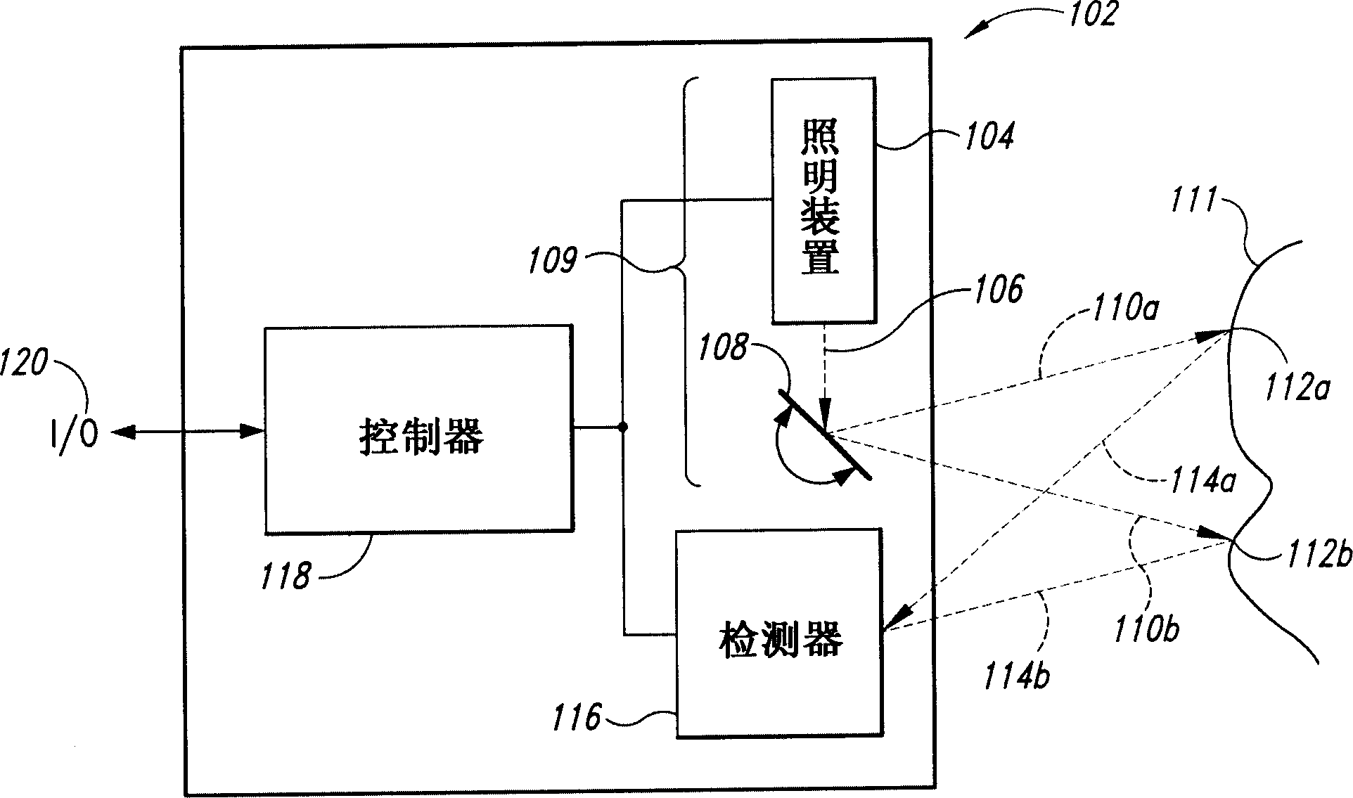
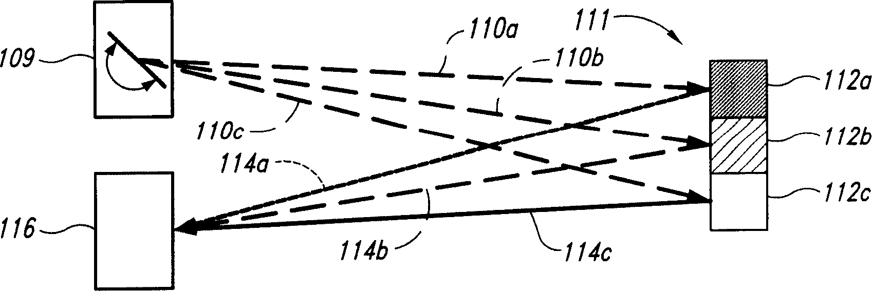
[0056] figure 1 A block diagram of the scanned beam imager 102 is shown. The illumination source 104 generates a first light beam 106 . The scanner 108 reflects the first beam to generate a second scanned beam 110 across the field of view (FOV), indicated by the two positions 110a and 110b in the figure. Scanning beam 110 in turn illuminates viewpoint 112 on the FOV, represented by positions 112a and 112b corresponding to beam positions 110a and 110b, respectively. When beam 110 illuminates spot 112, the illuminating beam 110 is reflected, absorbed, scattered, refracted, or otherwise affected by properties of the object or material to produce scattered light energy. A portion 114 of this scattered light energy, represented on the diagram by scattered rays 114a and 114b emanating from point locations 112a and 112b respectively, travels to one or more detectors 116 which receive the rays and then The amount of light energy produces a corresponding electrical signal. This ele...


PUM


Abstract

A scanning endoscope amenable to both rigid and flexible forms, scans a beam of light across a field-of-view, collects light scattered from the scanned beam, detects the scattered light, and produces an image. The endoscope may comprise one or more bodies housing a controller, light sources, and detectors; and a separable tip housing the scanning mechanism. The light sources may include laser emitters that combine their outputs into a polychromatic beam. Light may be emitted in ultraviolet or infrared wavelengths to produce a hyperspectral image. The detectors may be housed distally or at a proximal location with gathered light being transmitted thereto via optical fibers. A plurality of scanning elements may be combined to produce a stereoscopic image or other imaging modalities. The endoscope may include a lubricant delivery system to ease passage through body cavities and reduce trauma to the patient. The imaging components are especially compact, being comprised in some embodiments of a MEMS scanner and optical fibers, lending themselves to interstitial placement between other tip features such as working channels, irrigation ports, etc.

Description

technical field [0001] This invention relates to scanned beam systems, and more particularly to endoscopes and laparoscopes that use scanned beam imaging. Background technique [0002] This application is based on Provisional Patent Application No. 60 / 482,376, inventors Wiklof et al., entitled "Scanning Endoscopes," filed June 23, 2003, and claims priority on that filing date right. [0003] Video endoscopy and laparoscopy have been commonly used since the 1980s. Laparoscopes are rigid devices that can be used for minimally invasive procedures. Typically, laparoscopes use a handle whose proximal external port contains a digital camera. The digital camera captures video images through a tube protruding into the patient's body cavity that contains a series of end-to-end rod lenses. The camera sends signals via wires to a console that usually includes a monitor. Also typically located on the console is a light source, usually a xenon lamp. The light source transmits light...

Claims


Application Information

Patent Timeline
Patent Type & Authority Applications(China)
IPC IPC(8): A61B1/07A61B1/00G02B23/26G02B26/08A61B1/012
Inventor 克里斯托弗·A·维克勒夫马利克·I·阿姆贾德约翰·R·刘易斯弗兰克·B·梅廷克里斯琴·S·L·赖尔森徐建华克拉伦斯·T·泰格林
Owner MICROVISION
Why Eureka
Try Eureka