Roller screw

A technology of roller screw and roller, applied in belt/chain/gear, mechanical equipment, transmission, etc., can solve the problem of undeveloped preload applied by roller screw

Inactive Publication Date: 2006-11-29
THK CO LTD
View PDF2 Cites 6 Cited by
  • Summary
  • Abstract
  • Description
  • Claims
  • Application Information

AI Technical Summary

Problems solved by technology

Regarding roller screws using rollers as rolling elements, for example, the roller screws described in Patent Documents 1 and 2 have not yet been commercialized, and the technology for applying preload to the roller screws has not yet been developed.

Method used


Image

  • Roller screw
  • Roller screw
  • Roller screw

Examples


Embodiment Construction

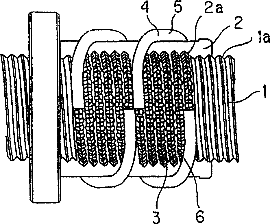
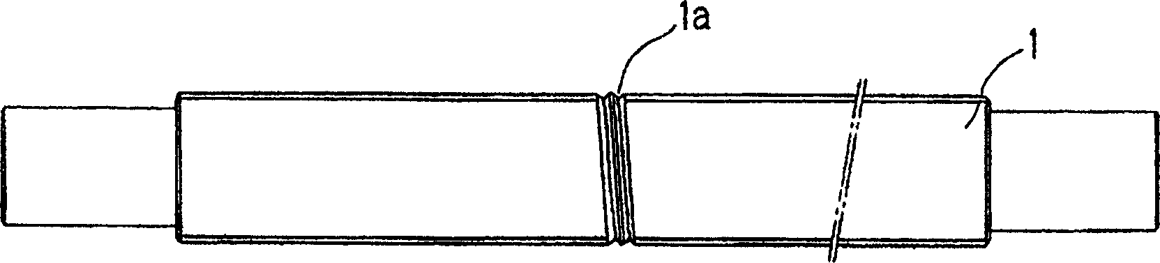
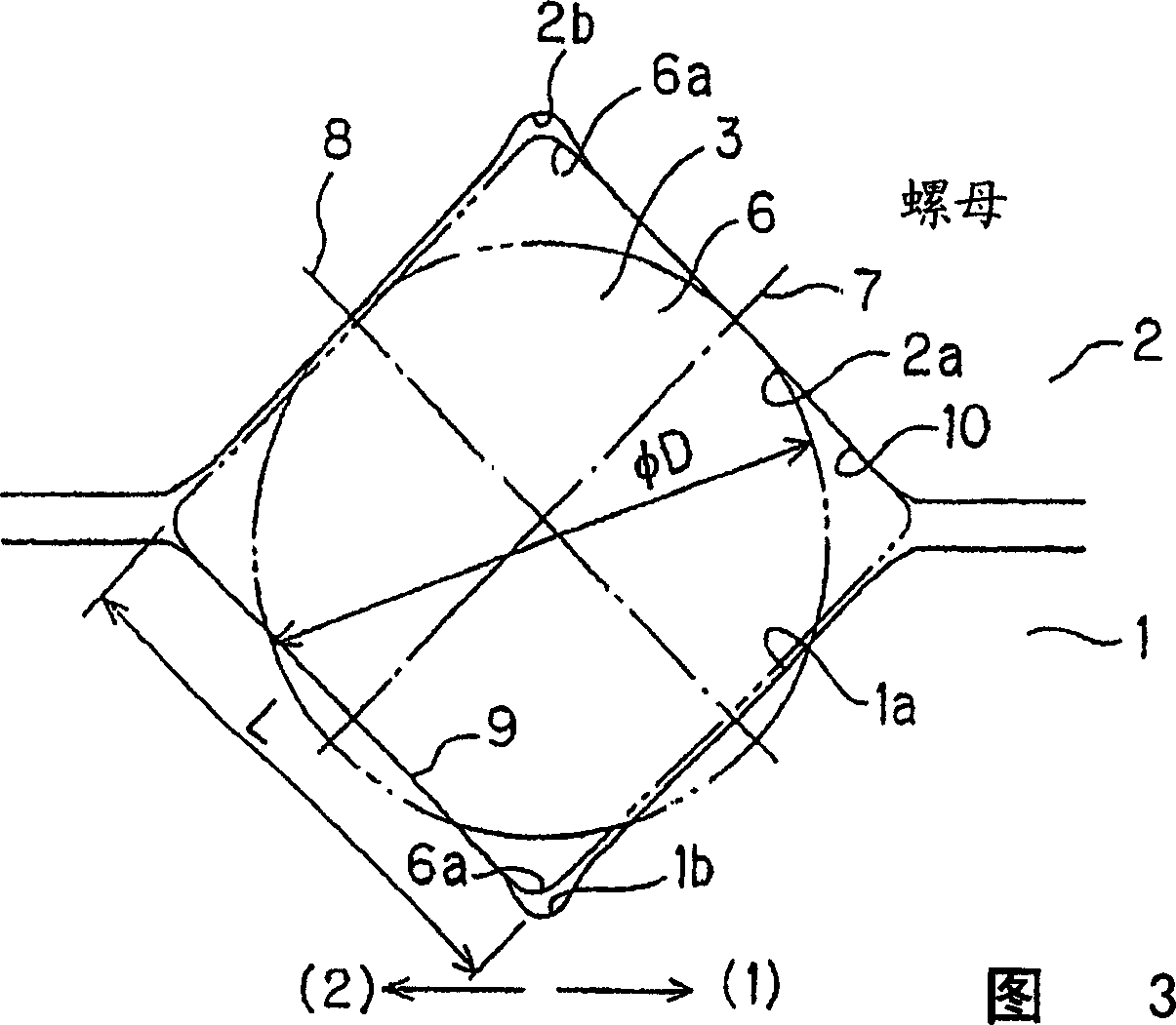
[0036] figure 1 A roller screw according to one embodiment of the present invention is shown. The roller screw has: a screw shaft 1 with a helical roller rolling groove 1a formed on the outer peripheral surface; The roller raceway groove 2a is relatively rotatably installed on the screw shaft 1. On the nut part 2, a return pipe 4 is mounted as a return part, and the return pipe rolls the loaded roller between the roller raceway groove 1a of the screw shaft 1 and the loaded roller raceway groove 2a of the nut part 2. One end of the channel 3 is connected to the other end. Inside the return pipe 4, a roller return passage 5 having a quadrangular cross-section, which is a square roller return passage 5 in this embodiment, is formed along the axial direction.

[0037] On the loaded roller rolling passage 3 between the roller rolling groove 1a of the screw shaft 1 and the loaded roller rolling groove 2a of the nut member 2, and the roller return passage 5 in the return pipe 4, t...


PUM


Abstract

A roller screw comprises a screw shaft (1) externally formed with a spiral roller rolling groove (1a), a nut member (2) internally formed with a spiral load roller rolling groove (2a) opposed to the roller rolling groove (1a), and a plurality of rollers (6) received between the roller rolling groove (1a) and the load roller rolling groove (2a). The plurality of rollers (6) are cross-arranged, and their diameter (D) is oversized, being greater than specified dimension. According to such a screw, it is possible to pre-load to an optimum degree according to the construction of the roller screw, and therefore, the rigidity of the roller screw can be improved.

Description

technical field [0001] The present invention relates to a roller screw interposed between a screw shaft and a nut member so that rollers can roll and move. Background technique [0002] A ball screw is disclosed in which balls are interposed between a screw shaft and a nut member so as to be rotatable. The balls are interposed between a helical ball rolling groove formed on the outer peripheral surface of the screw shaft and a helical loaded ball rolling groove formed on the inner peripheral surface of the nut member. When the screw shaft rotates relative to the nut member, a plurality of balls roll on the ball rolling groove of the screw shaft and the loaded ball rolling groove of the nut member. [0003] If a ball screw is used, the coefficient of friction when the screw shaft is rotated relative to the nut member can be reduced, so it is actually applied to a positioning mechanism of a machine tool, a feed mechanism, or a steering device of a bicycle. However, since the...

Claims


Application Information

Patent Timeline
Patent Type & Authority Applications(China)
IPC IPC(8): F16H25/22
CPCF16H2025/2271F16H25/2247F16H25/2238Y10T74/19767F16H25/22
Inventor 寺町彰博道冈英一丹羽宏西村健太郎
Owner THK CO LTD
Why Eureka
Try Eureka