Embraced moving cylinder and methods of using same

a technology of moving cylinders and cylinders, which is applied in the direction of positive displacement liquid engines, pumps, machines/engines, etc., can solve the problems of primarily limited use of oscillating cylinders, outweighed the advantages, and existing designs that cannot achieve the high pressure required for efficient operation

Inactive Publication Date: 2004-09-23
MALING CHARLES
View PDF30 Cites 2 Cited by
  • Summary
  • Abstract
  • Description
  • Claims
  • Application Information

AI Technical Summary

Benefits of technology

[0077] As shown below, the invention of this application, by having the cylinder embraced or surrounded as completely as possible by a housing, limits the potential leakage to the outside to a small area. Furthermore, the embracement itself prevents the cylinder from being blown away from the housing. Since the flow controlling interface is that between the cylinder and the embracing housing, it is impossible for the surfaces of that interface to separate. Finally, by using end porting, high pressure ports along the flow directing interface have no leverage over any bearings at the pivot axis of oscillation.
[0179] Additionally, this invention inherently facilitates a number of other efficiency and emissions gains. Since compression and power can be done in separate cylinders, different expansion and compression volumes are easily and naturally achieved. With intake and exhaust being done in separate chambers, it is easier to avoid fuel contamination of exhaust where fuel is mixed with air prior to intake. Where the two cylinders need not reach TDC at the same time, ignition can occur after compression is complete but before the power stroke begins. This will facilitate more complete combustion and enable more work to be obtained from the power stroke. By enabling two-sided operation, more compact 4-stroke engines are possible and the losses from reversing reciprocating masses, compressing valve springs and such can be reduced, along with permitting the number of pistons scraping cylinder walls to be halved. Finally, there is an increased mechanical advantage in having the piston attached directly to the crankshaft and a related reduction of piston-cylinder wall friction.

Problems solved by technology

The disadvantage was that existing designs did not succeed in maintaining the high pressures required for efficient operation.
This disadvantage has so outweighed the advantages that current use of oscillating cylinders is primarily limited to toy steam engines and locomotives where little or no useful work is being powered.
Too great and the surfaces could not move relative to each other seizing the engine.
Too little and the interface would leak.
All these efforts suffered from an clear failing; the pressure to resist the separation of the flow controlling surfaces was applied at the pivot point of the oscillating cylinders while the pressure working to separate the surfaces was distant from the pivot.
The designs lack the mechanical simplicity which makes use of oscillating cylinders in steam engines appealing.
None of these designs offer any real advantage over the existing art.
Except in extremely large scale versions, useful compression ratios would not be obtainable without making passages which must sustain combustion too narrow to do so.
The engine has all the mechanical complexity and the relation of power to size and weight of a conventional four stroke with no apparent gain in efficiency or reduced emissions.
However, the embracement is made more complicated and less effective by sleeve valves between the trunnion head and the surrounding fixed housing.
Additionally, the embracement of Dock is only at one end of a rather complex cylinder, which even includes a water jacket.
The oscillating cylinder of that patent rivals that of Dock's in its complexity.
Also, neither it nor Dock's cylinder are suitable for two-sided use, which is a major drawback.

Method used


Image

  • Embraced moving cylinder and methods of using same
  • Embraced moving cylinder and methods of using same
  • Embraced moving cylinder and methods of using same

Examples


Embodiment Construction

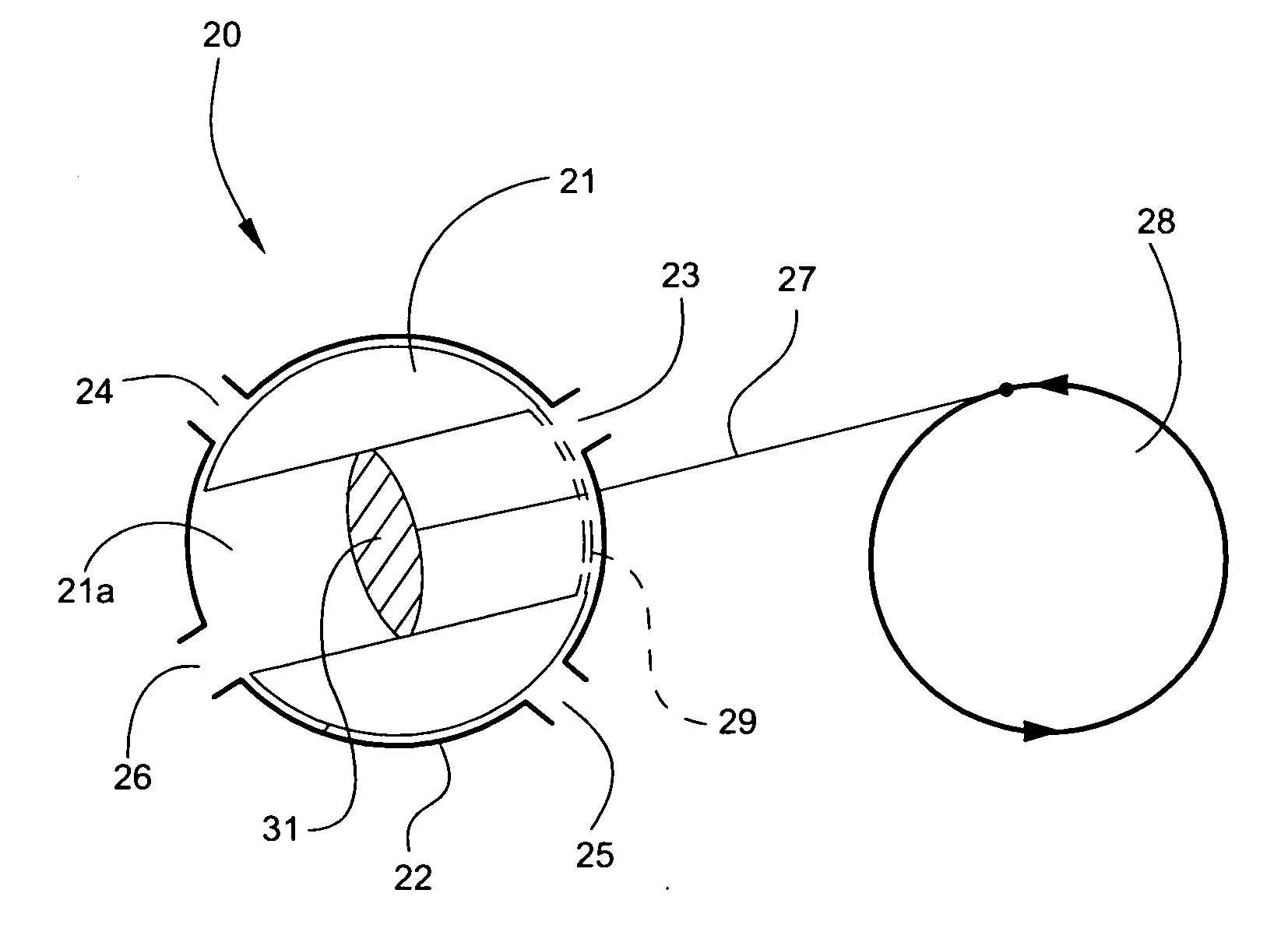
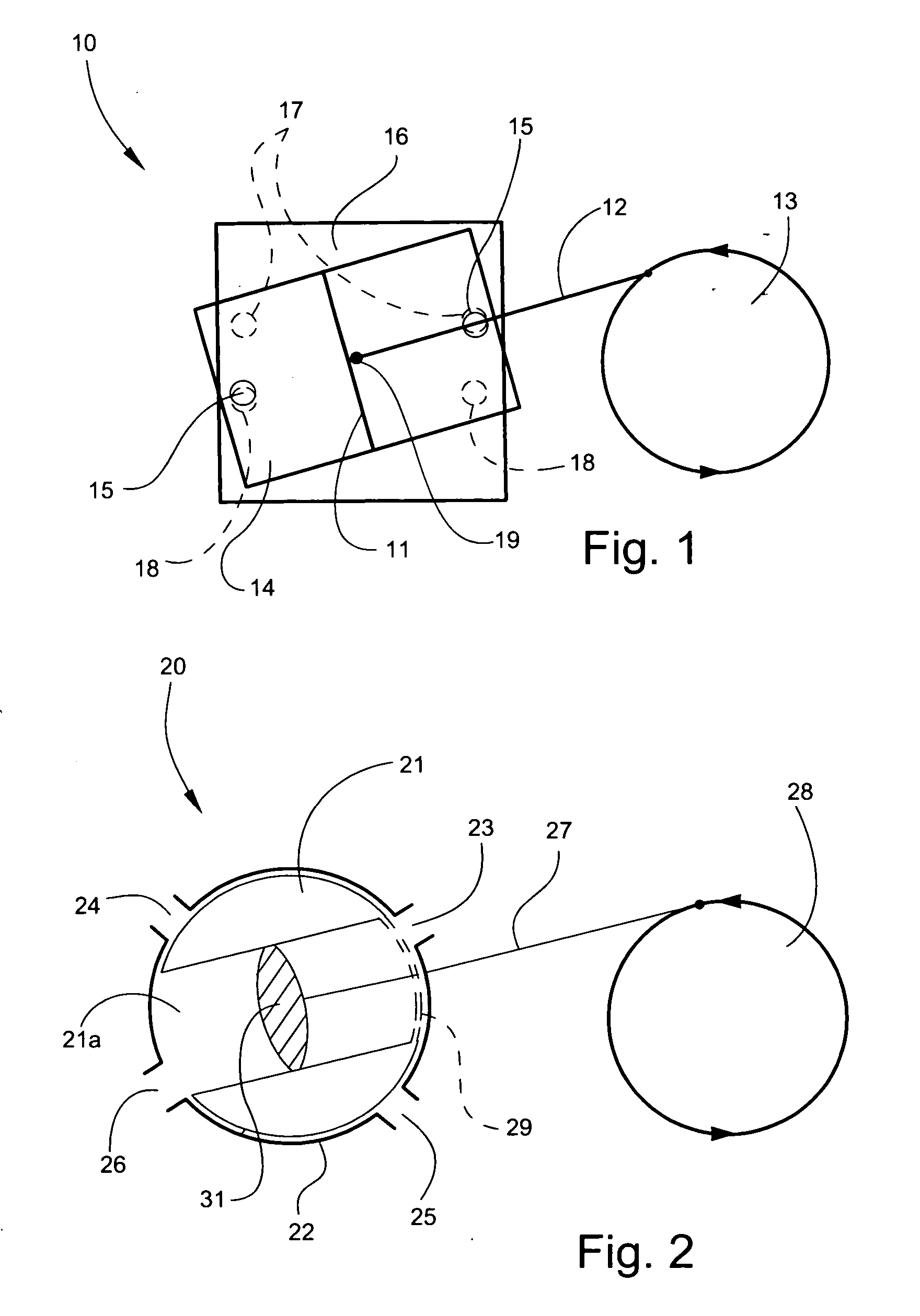
[0075] A prior art two sided oscillating cylinder assembly is illustrated in FIG. 1, and shown generally at reference numeral 10. The cylinder assembly 10 includes a piston head 11 and a rod 12 attached directly to a drive wheel or crankshaft 13. A cylinder 14 is generally held in place by some sort of bearing at a center pivot point 19 which allows the cylinder 14 to rock or oscillate with the movement of the piston head 11. Holes 15 at both ends of the cylinder 14 slide against a surface 16 containing entrance and exit ports 17, 18, respectively, located such as to be open to the cylinder holes 15 at the appropriate points in the movement of the piston 11. The cylinder 14 will also have a flat surface in the same plane as the holes 15 so as to seal the ports 17, 18 when not in use. This flat surface of the cylinder and the ported surface 16 together make up a flow distributing interface. The difficulty with this arrangement is that high pressures tend to blow the cylinder 14 away ...


PUM


Abstract

A moving cylinder assembly includes a cylinder having a chamber for receiving and engaging a piston, and a housing immediately embracing the cylinder and defining a slot through which the piston is positioned to allow for oscillating movement of the piston within the slot. The cylinder engages in reciprocal oscillating movement with the piston. The immediate embracement of the cylinder by the housing minimizes leakage between the cylinder and the housing. The cylinder assembly is suitable for use in an engine, compressor, pump or vacuum pump.

Description

TECHNICAL FIELD AND BACKGROUND OF THE INVENTION[0001] This application claims the benefit of U.S. Provisional Application No. 60 / 456, 125, filed Mar. 20, 2003. This invention relates to a moving cylinder for providing an efficient piston drive mechanism of the utmost simplicity. A partial list of applications of the invention includes use in external and internal combustion engines, pumps, compressors and vacuum pumps. The invention comprises a moving cylinder sufficiently embraced or surrounded by a generally fixed housing so as to prevent blow-by or leakage, and in some embodiments to provide a bearing. The embracement can be virtually complete and includes both ends. The most useful embodiments comprise oscillating cylinders embraced by housings rounded on the inside comprising, or within, pressure controlled containers. The pressure control could be passively accomplished by simply sealing or it could be active. The embodiments of the presented invention have types of end portin...

Claims


Application Information

Patent Timeline
Patent Type & Authority Applications(United States)
IPC IPC(8): F01B9/02F01B15/04F02B33/12F02B53/02F02B59/00F04B5/02F04B7/00F04B39/12
CPCF01B9/026F01B15/04F02B33/12F02B53/02Y02T10/17F04B5/02F04B7/008F04B39/122F02B59/00Y02T10/12
Inventor MALING, CHARLES
Owner MALING CHARLES
Why Eureka
Try Eureka