A shock mitigation apparatus

a technology of shock mitigation and shock absorber, which is applied in the direction of shock absorbers, vessel parts, vessel construction, etc., can solve the problems of high-performance watercraft, physical injury, and passengers subjected to repetitive high g-forces, and achieve the effect of convenient configuration

Active Publication Date: 2017-07-13
ZWAAN FRANCIS PAUL
View PDF20 Cites 2 Cited by
  • Summary
  • Abstract
  • Description
  • Claims
  • Application Information

AI Technical Summary

Benefits of technology

[0030]Finally, the apparatus is easily configurable depending on user preference. For example, the seat members may be modular allowing interchangeable units of a pommel design, a leaning post attachment and / or a regular design seat without having to replace the entire seat member.

Problems solved by technology

High-speed, high performance watercraft, as used in both military and civilian application, subject the passengers to repetitive high G-forces resulting from the sudden deceleration of the watercraft as it falls off waves or hits waves while going at a high forward speed and a high angle of attack.
Such repetitive impacts are both debilitating to the watercraft's occupants, preventing them from carrying out their tasks, and further may result in physical injury.
As above, these effects can cause fatigue and injuries to the watercraft's passengers and crew especially when subjected to prolonged periods of constant impacts.
Whilst a well designed and built watercraft can mostly withstand the shocks caused by these impacts, the passengers and crew experience an uncomfortable ride which reduces physical, cognitive and psychomotor performance and increases the risk of acute and chronic musculoskeletal injuries.
At worst, it can result in serious injury or death.
The muscle tissue and organs themselves act as shock absorbers that try to dampen vibration and can become fatigued over time.
As fatigue continues, the potential for declining work performance and injury increases due to the unpredictable nature of shocks that come from high speed navigation in significant waves.
However, a disadvantage of U.S. Pat. No. 5,810,125 is that to mitigate shock, the system requires the use of an array of components such as complex electronic controllers, sensor units, electrohydraulic servo actuators and the like.
This increases the costs and potential for failure and may require ongoing maintenance especially in a marine environment.
A disadvantage of arms that are pivoted at both ends is that they do not flex during compression and therefore do not provide any restorative force.
This spring along with the four pivot points adds weight, cost and complexity to the design.
Furthermore, each additional pivot can contribute to additional ‘free-play’ which can produce noise and unwanted movement.
In order to achieve the required flex, springs configured such as those disclosed in U.S. Pat. No. 5,505,521 are required to be manufactured out of a thin material resulting in a spring having to perform under high stress.
Also, the clamps at the ends of the spring are under high clamping forces and stress requiring the clamps to be manufactured from heavy bent and welded marine-grade stainless steel plate, thus adding to both the weight and cost of the apparatus.
Also, a further problem with all of the mechanical arrangements described above is that they only allow primary shock mitigation in one direction i.e. vertical movement only.
A lateral impact force can lead to excessive lateral movement of the torso and neck resulting in spinal injuries.
However, as above the majority of the shock mitigation apparatus manufactured by these companies only allow for primary shock mitigation i.e. vertical movement only.
Also due to their designs requiring construction from marine-grade stainless steel, they are complex, heavy, with many parts requiring labour-intensive manufacturing processes, making them expensive to manufacture.
This results in additional costs for manufacture and a more complex arrangement of componentry to achieve its objective than is necessary.
Furthermore, this mitigation seat system does not allow for ease of tuneability to alter and / or control flexure within the spring in three planes of movement (longitudinal surge, vertical heave and lateral sway) and axes of rotation (roll, pitch and yaw) depending on occupant and / or particular application.

Method used


Image

  • A shock mitigation apparatus
  • A shock mitigation apparatus
  • A shock mitigation apparatus

Examples


working examples

[0133]The above described shock mitigation apparatus and uses are now described by reference to specific embodiments and examples.

[0134]Example 1—Single Cantilever Leaf Spring Combined with Stabiliser Arm

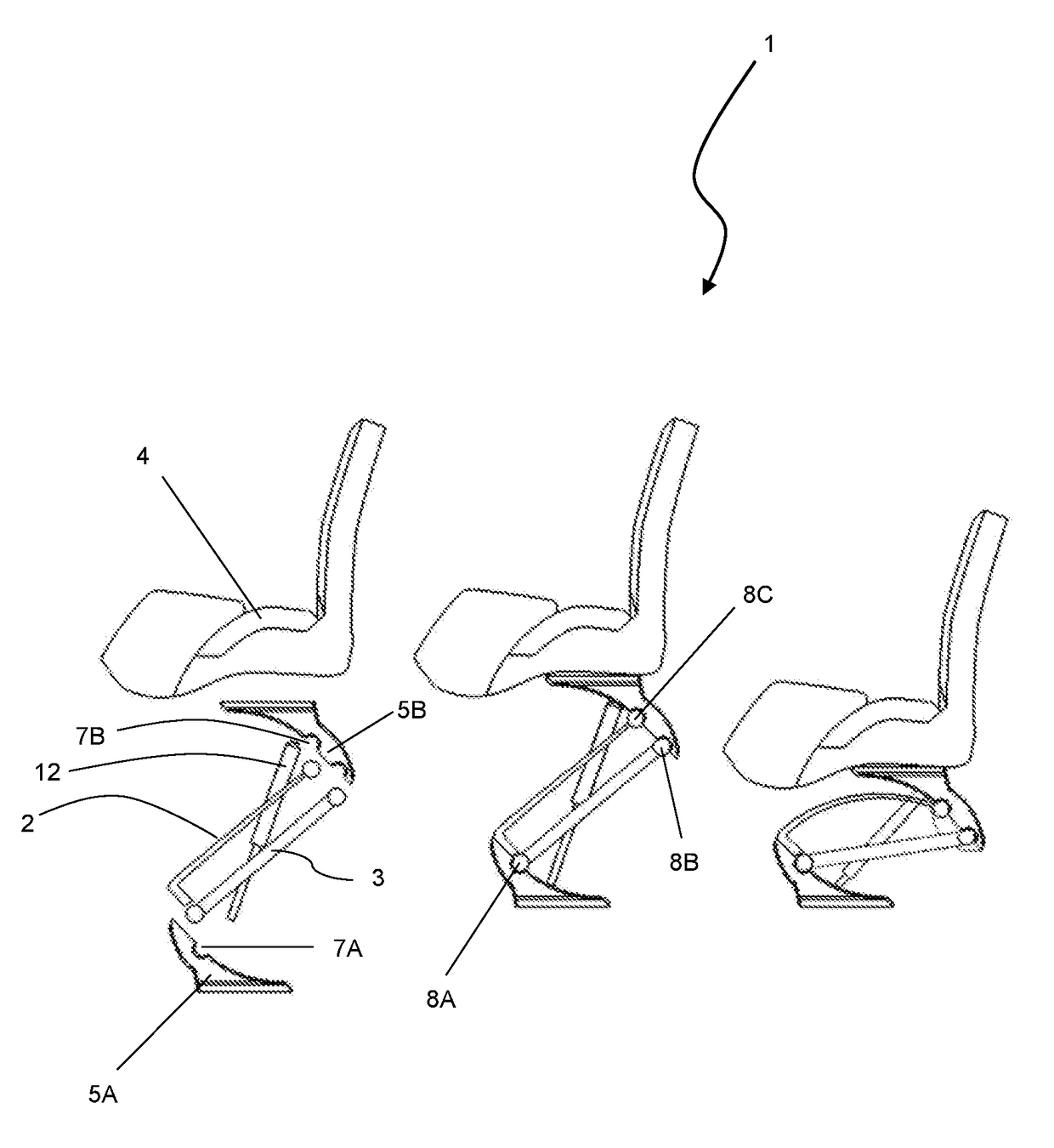
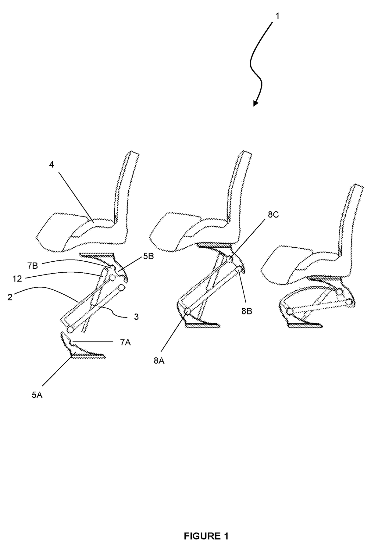
[0135]Referring to FIG. 1, a series of side views of a shock mitigation apparatus 1 that includes one leaf spring 2 and a stabiliser arm 3 are shown (from left to right): an unassembled apparatus 1 with exploded view of components, an assembled apparatus 1 upon an upward rebound stroke, and an assembled apparatus 1 during a compression stroke.

[0136]The shock mitigation apparatus 1 also includes a seat member 4 in the form of a pommel design as illustrated and lower and upper mount members 5A,B manufactured out of injection moulded plastic in known fashion. The lower mount member 5A is attached to the sole of a boat (not shown) with fasteners and reinforcing plates / washers (not shown) in known fashion. Optionally, and best seen in FIG. 12, the lower mount member 5A may be securely mo...


PUM


Abstract

Described herein is a shock mitigation apparatus. The shock mitigation apparatus may be utilised in a marine environment, able to absorb shocks transmitted to a seat system from a structure to which the seat is affixed. The shock mitigation apparatus includes at least one leaf spring wherein the leaf spring is cantilevered at one end and pivoted at a distal end thereof, and wherein the pivoted end is free to articulate upon flexure of the leaf spring.

Description

TECHNICAL FIELD[0001]Described herein is a shock mitigation apparatus. More specifically, a shock mitigation apparatus which relates to a new and improved seating system, such as may be utilised in a marine environment, able to absorb shocks transmitted to the seat system from a structure to which the seat is affixed. The shock mitigation apparatus includes at least one leaf spring wherein the leaf spring is cantilevered at one end and pivoted at a distal end thereof, and wherein the pivoted end is free to articulate upon flexure of the leaf spring.BACKGROUND ART[0002]High-speed, high performance watercraft, as used in both military and civilian application, subject the passengers to repetitive high G-forces resulting from the sudden deceleration of the watercraft as it falls off waves or hits waves while going at a high forward speed and a high angle of attack. Such repetitive impacts are both debilitating to the watercraft's occupants, preventing them from carrying out their tasks...

Claims


Application Information

Patent Timeline
Patent Type & Authority Applications(United States)
IPC IPC(8): B60N2/54F16F13/00F16F13/02B63B29/06F16F15/02
CPCB60N2/546B63B29/06F16F15/022F16F13/02F16F2238/022B63B2029/043B63B2709/00F16F2224/02F16F13/00B63B29/04B60N2/502B60N2/507B60N2/24B60N2002/247
Inventor ZWAAN, FRANCIS PAUL
Owner ZWAAN FRANCIS PAUL
Why Eureka
Try Eureka