Waveguide conversion device, waveguide rotary joint, and antenna device

A waveguide conversion and waveguide technology, which is used in connection devices, waveguide horns, waveguide openings, etc., can solve problems such as reduced transmission efficiency, reduced signal properties, and increased signal loss.

Inactive Publication Date: 2006-11-29
MURATA MFG CO LTD
View PDF1 Cites 12 Cited by
  • Summary
  • Abstract
  • Description
  • Claims
  • Application Information

AI Technical Summary

Problems solved by technology

Thus, in the conventional technology, when a high-frequency signal is transmitted between a rectangular waveguide and a circular waveguide, there are problems such as unnecessary resonance due to an unnecessary transmission mode, and signal loss is increased, resulting in, for example, a decrease in transmission efficiency, Decreased signal quality

Method used


Image

  • Waveguide conversion device, waveguide rotary joint, and antenna device
  • Waveguide conversion device, waveguide rotary joint, and antenna device
  • Waveguide conversion device, waveguide rotary joint, and antenna device

Examples


Embodiment Construction

[0068] A waveguide conversion device, a waveguide rotary joint and an antenna device according to preferred embodiments of the present invention will be described in detail below with reference to the accompanying drawings.

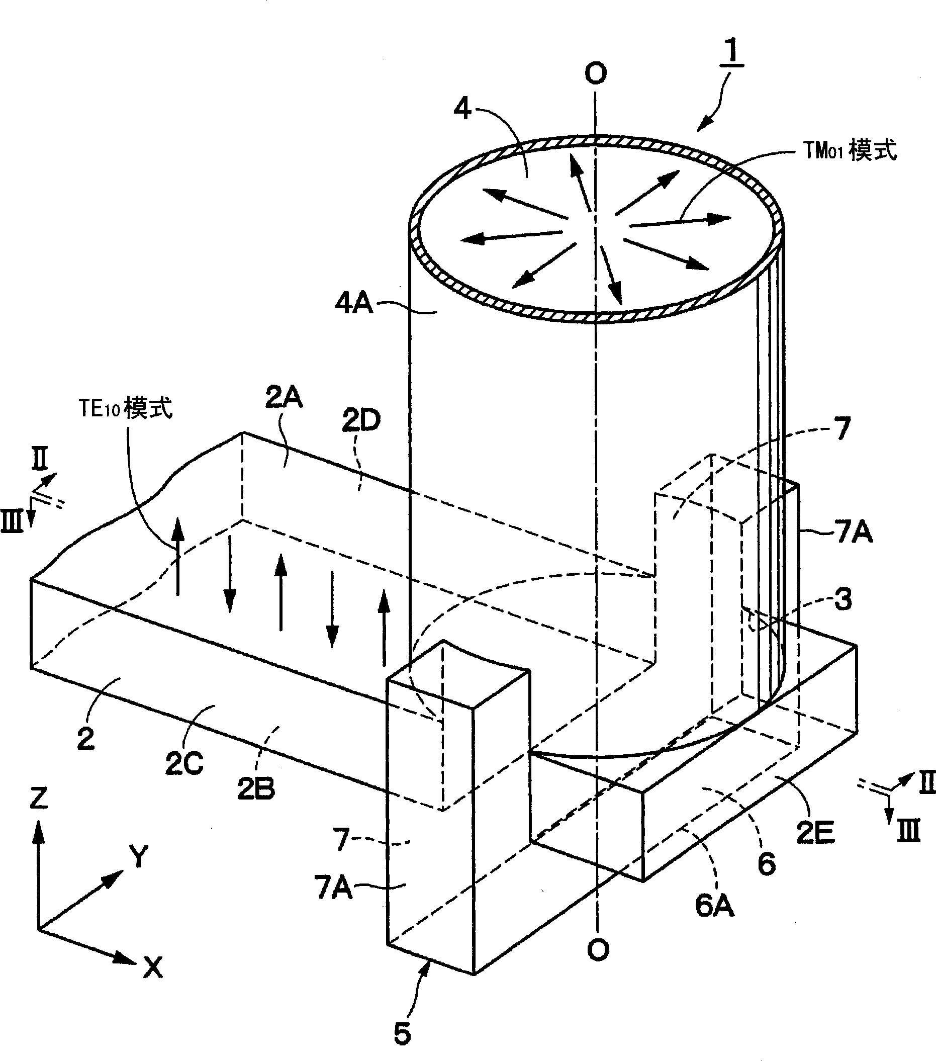
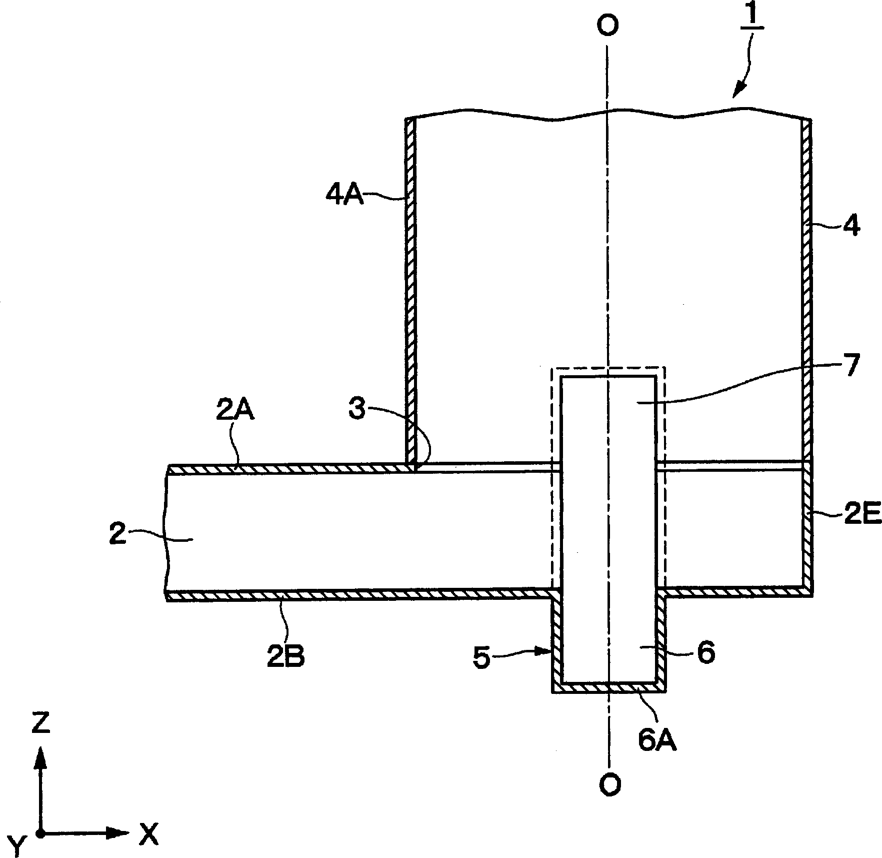
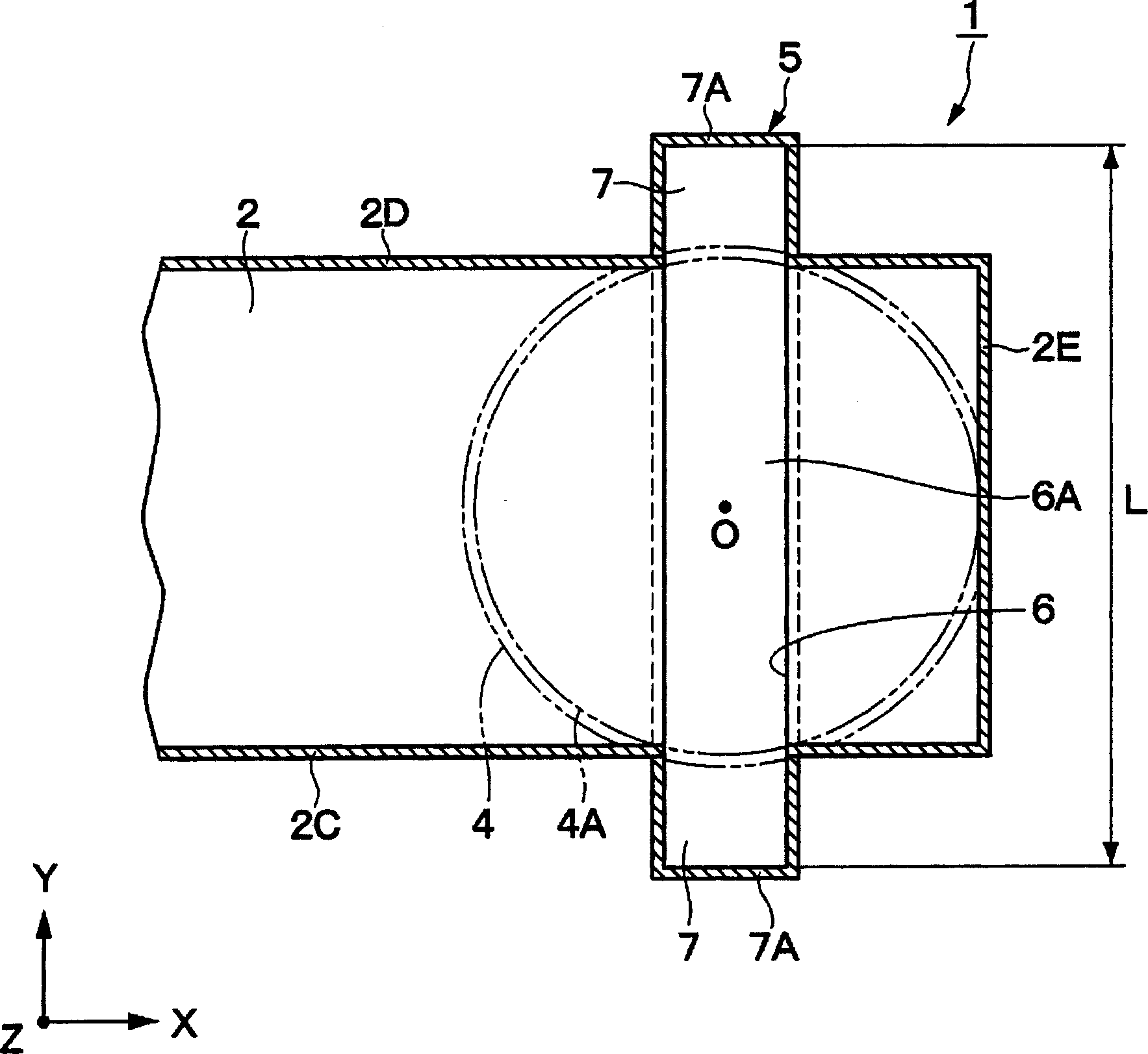
[0069] Figures 1 to 3 Indicates the first embodiment. exist Figures 1 to 3 In , reference numeral 1 denotes a waveguide conversion device. The waveguide conversion device 1 includes, for example, a rectangular waveguide 2, a circular waveguide 4, and an unnecessary wave suppressing groove 5, which will be described below. The waveguide conversion device 1 transmits high-frequency signals, such as microwaves and millimeter waves.

[0070] The rectangular waveguide 2 is formed of, for example, a rectangular metal pipe. Rectangular waveguide 2 transmission TE 10 The high-frequency signal of the mode, and extends, for example, along the X-axis direction among the X, Y, and Z axes perpendicular to each other. The cross-sectional shape of the rectangula...


PUM


Abstract

To improve the transmission efficiency of a necessary transmission mode by providing an unnecessary-wave suppression groove that prevents an unnecessary transmission mode from being excited at a mode conversion part between a rectangular waveguide and a circular waveguide. A rectangular waveguide 2 is connected to a circular waveguide 4 at right angles, and an unnecessary-wave suppression groove 5 that extends along tube walls 2B, 2C, and 2D of the rectangular waveguide 2 and a tube wall 4A of the circular waveguide 4 is provided at a mode conversion part between the rectangular waveguide 2 and the circular waveguide 4. Thus, the unnecessary-wave suppression groove 5 can prevent an unnecessary TE 11 mode from being excited in the circular waveguide 4 due to electromagnetic waves of the TE 10 mode that transmit through the rectangular waveguide 2, thereby reducing conversion loss due to the TE 11 mode. Accordingly, electromagnetic waves of the TM 01 mode can be efficiently excited in the circular waveguide 4, and signals can be stably transmitted between the waveguides 2 and 4.

Description

technical field [0001] The invention relates to a waveguide conversion device, a waveguide swivel and an antenna device suitable for connecting eg rectangular waveguides to circular waveguides, the waveguides being designed for high frequency signals. Background technique [0002] Generally, an antenna device is known as a waveguide conversion device including a rectangular waveguide having a rectangular cross-sectional shape and a circular waveguide having a circular cross-sectional shape, which are connected to each other (see Patent Document 1, for example). [0003] Patent Document 1: Japanese Unexamined Patent Application Publication No. 5-235603. [0004] In such a conventional antenna device, for example, a conical aperture is provided at one end of a circular waveguide as a radiator, and a rectangular waveguide extending in a direction perpendicular to the circular waveguide is connected to the other end of the circular waveguide. When the aperture of the circular w...

Claims


Application Information

Patent Timeline
Patent Type & Authority Applications(China)
IPC IPC(8): H01P1/162H01P1/04H01P5/02H01P5/08H01Q13/02H01Q13/06
CPCH01P5/082H01Q13/06H01P1/066
Inventor 冈野健永井智浩平塚敏朗
Owner MURATA MFG CO LTD
Why Eureka
Try Eureka