Plasma display panel (pdp)

A display panel and plasma technology, applied in AC plasma display panels, gas discharge electrodes, solid cathode components, etc., can solve the problems of PDP low contrast

Inactive Publication Date: 2006-12-06
SAMSUNG SDI CO LTD
View PDF0 Cites 0 Cited by
  • Summary
  • Abstract
  • Description
  • Claims
  • Application Information

AI Technical Summary

Problems solved by technology

[0005] However, these PDPs have the disadvantage of relatively low contrast

Method used


Image

  • Plasma display panel (pdp)
  • Plasma display panel (pdp)
  • Plasma display panel (pdp)

Examples


Embodiment Construction

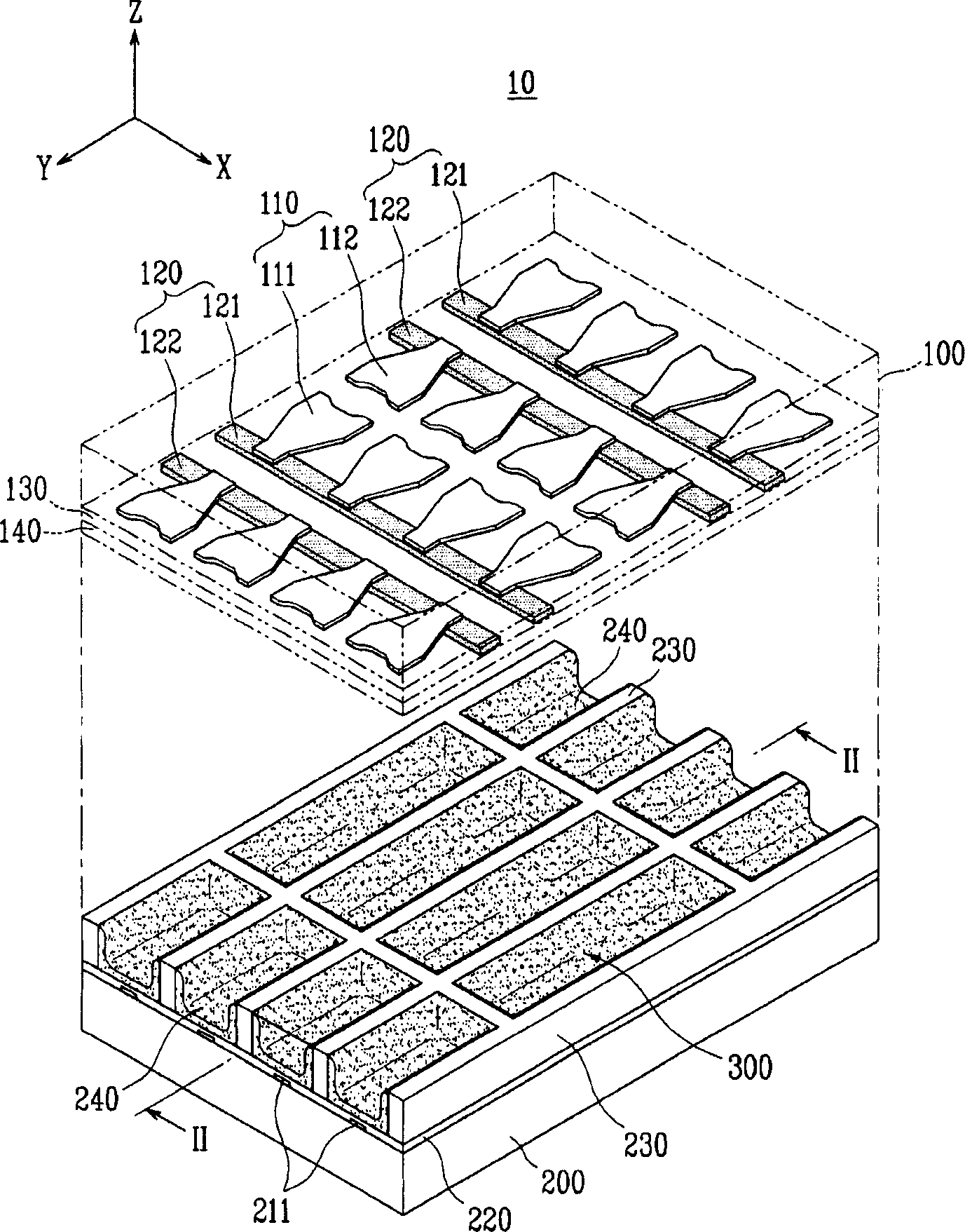
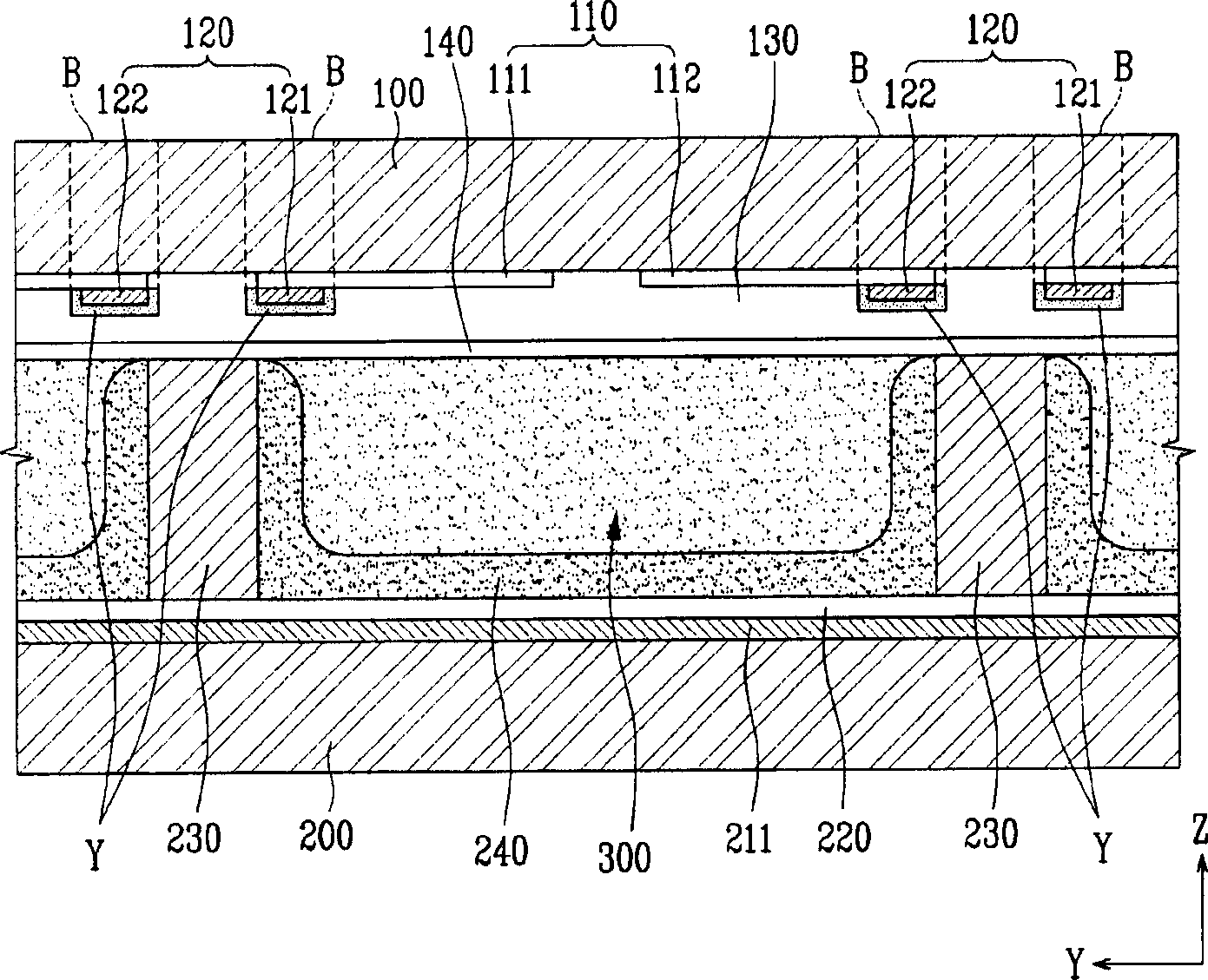
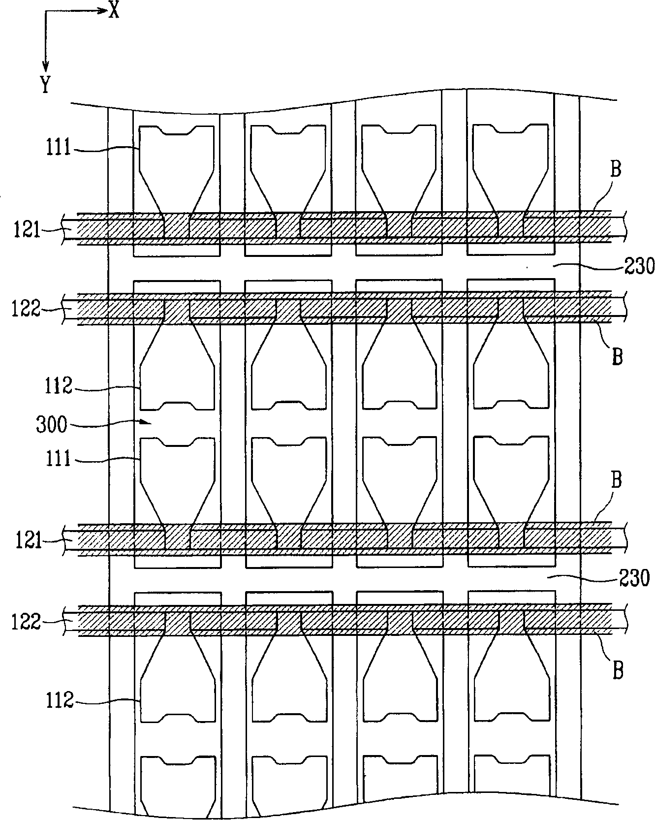
[0027] Hereinafter, a plasma display panel (PDP) according to an embodiment of the present invention will be described in detail with reference to the accompanying drawings. The figure schematically shows a three-electrode surface discharge AC PDP. However, these examples are only chosen to illustrate the present invention, and the present invention is not limited to these examples.

[0028] Throughout the specification, the same reference numerals are used to designate the same or similar parts. The first embodiment was explained, and for the subsequent embodiments, descriptions are provided only for components different from the first embodiment. In order to clearly illustrate the present invention, irrelevant information has been omitted.

[0029] Such as figure 1 As shown, a plasma display panel (PDP) 10 according to a first embodiment of the present invention includes: a front substrate 100 having at least one portion colored with a predetermined color; substrate 200,...


PUM


Abstract

A Plasma Display Panel (PDP) includes a front substrate having at least a portion colored; a rear substrate arranged to face the front substrate and spaced apart from the front substrate by a gap that is divided into a plurality of discharge spaces; a phosphor layer arranged inside the discharge space; a plurality of transparent electrodes arranged on the front substrate at locations respectively corresponding to the plurality of discharge spaces; bus electrodes connected to the transparent electrodes; and a dielectric layer covering the transparent electrodes and the bus electrodes. The front substrate is colored with a color which is complementary, based on subtractive mixing, to a color of the dielectric layer when it is discolored.

Description

technical field [0001] The present invention relates to a plasma display panel (PDP), and more particularly, to a PDP that improves bright room contrast and can be manufactured in a simplified process while reducing its failure rate. Background technique [0002] Plasma Display Panels (PDPs) are classified into direct current (DC) PDPs, alternating current (AC) PDPs, and hybrid PDPs according to the type of driving voltage applied to discharge cells. Also, the PDP is classified into a relative discharge PDP and a surface discharge PDP according to a discharge structure. [0003] Since direct movement of charges between corresponding electrodes seriously damages electrodes in DC PDPs, AC surface discharge PDPs have been widely used recently. [0004] Such a PDP has excellent characteristics including high image quality, thin thickness, light weight, and wide viewing angle. Also, these PDPs are attracting more attention as next-generation thin display devices due to their si...

Claims


Application Information

Patent Timeline
IPC IPC(8): H01J17/49H01J17/04H01J17/02H01J11/12H01J11/22H01J11/24H01J11/26H01J11/34H01J11/36H01J11/38H01J11/40H01J11/42H01J11/44H01J11/50
CPCH01J11/44H01J11/24H01J2211/444H01J11/12H01J11/38H01J11/22H01J11/34
Inventor 柳成勋权赫冠
Owner SAMSUNG SDI CO LTD
Why Eureka
Try Eureka