Cooling unit of gaseous discharge lamp in high pressure

A technology of cooling device and high-pressure gas, which is applied to components of gas discharge lamps, cooling/heating devices of lighting devices, lighting devices, etc., and can solve the problems of insufficient cooling capacity of reflector 3, difficult installation, and small size of air passages , to avoid thermal stress cracking, increase service life, and slow down the effect of deterioration

Inactive Publication Date: 2006-12-06
GLORY PRAISE PHOTRONICS CORP
View PDF1 Cites 7 Cited by
  • Summary
  • Abstract
  • Description
  • Claims
  • Application Information

AI Technical Summary

Problems solved by technology

The size of the air channel is too small, the production cost is high, the installation is not easy, and it is also easily damaged by external forces
[0013] 2. The tubular air channel directly guides the cooling airflow to cool the discharge area 1a, which lacks a good cooling effect on the reflector 3
And the cooling of the discharge area 1a is excessively concentrated, so that the cooling capacity of the reflector 3 is insufficient, and a system fan must still be added to solve the problem that the reflective coating surface falls off due to the high temperature in the reflector 3
Therefore No. US6724147 patent case still does not really solve the cooling problem of discharge lamp tube 1 and reflector 3

Method used


Image

  • Cooling unit of gaseous discharge lamp in high pressure
  • Cooling unit of gaseous discharge lamp in high pressure
  • Cooling unit of gaseous discharge lamp in high pressure

Examples


Embodiment Construction

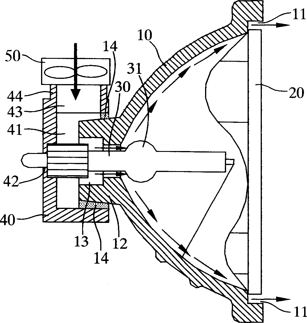
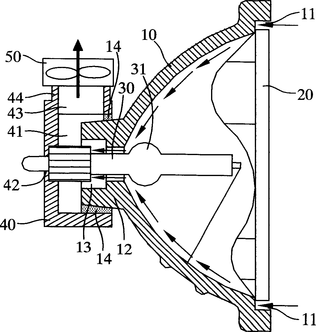
[0054] See figure 2 and image 3 As shown, a lighting device provided by the first preferred embodiment of the present invention includes a high-pressure gas discharge lamp group and a cooling device. The cooling device can control and continuously drive the cooling air flow to circulate inside and outside the high-pressure gas discharge lamp group. The temperature distribution inside the high-pressure gas discharge lamp group is controlled to operate in an appropriate temperature range, so that the high-pressure gas discharge lamp group has a better working life.

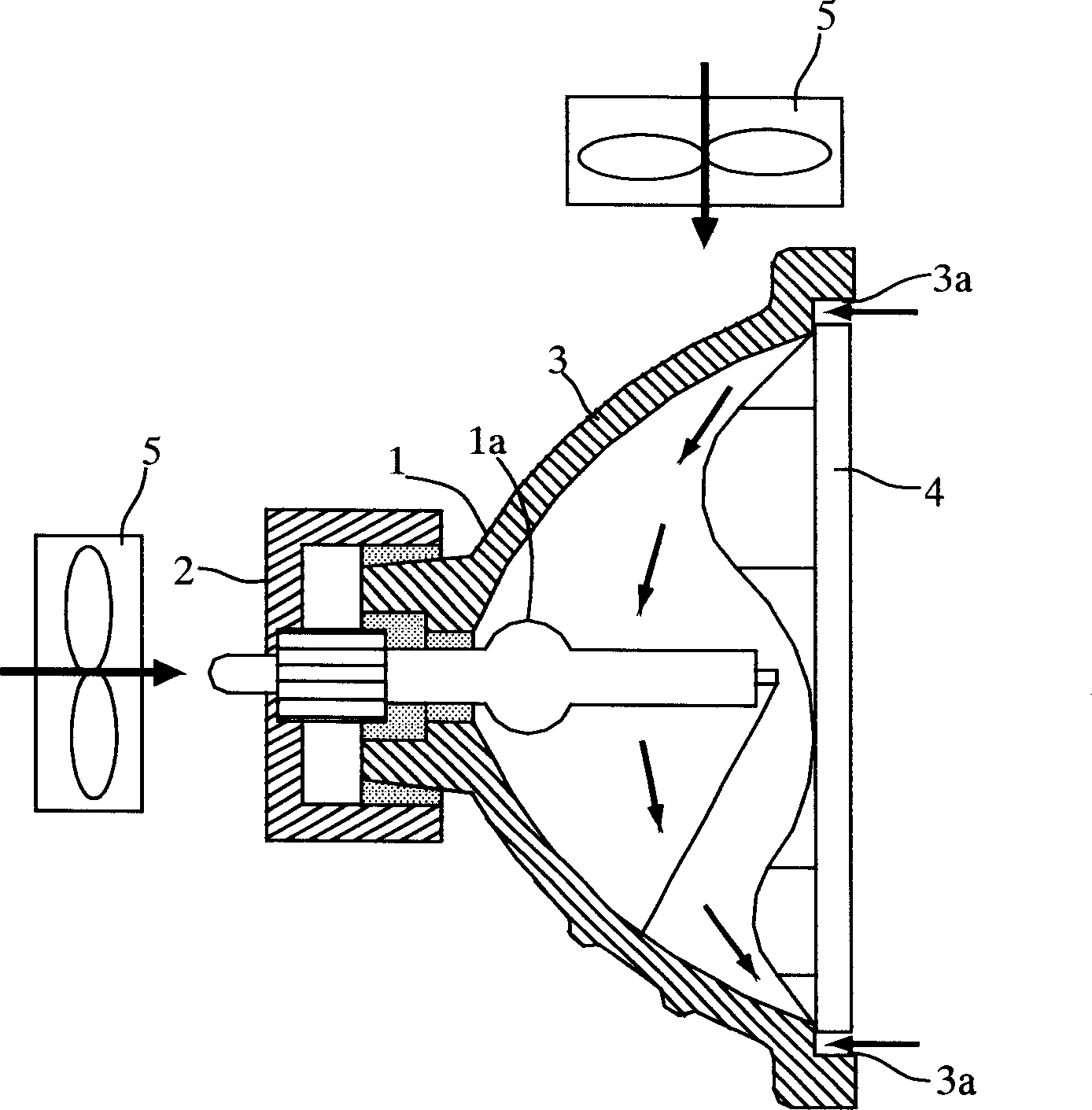
[0055] A common high-pressure gas discharge lamp group includes a reflector 10, a front lamp cover glass 20, and a discharge lamp tube 30. The reflector 10 usually presents a parabolic or elliptical shape, and the discharge lamp tube 30 has a spherical or elliptical discharge area 31, which is usually placed on the focus of the parabolic or elliptical surface of the reflector 10, and the discharge lamp 30 The electrod...


PUM


Abstract

The cooling unit includes diversion module, and airflow generation unit. The diversion module possesses depressed part and vent holes. The depressed part is in use for holding cervical part of bowl. Being generated from the airflow generation unit, passing through vent holes, and gap between discharge lamp tube and cervical part, cooling airflow generates cooling effect on discharge zone, and cervical part of bowl. Finally, hot airflow is left through air gap between cervical part of bowl and front glass of lamp cover. Or, airflow generation unit sucks cooling airflow. Through air gap between bowl and front glass of lamp cover, cooling airflow generates cooling effect on discharge zone, and cervical part of bowl. Finally, passing through gap between tube and cervical part, hot airflow is left through the vent holes. Cooling airflow keeps bowl and discharge zone at optimal operation temperature so as to increase luminosity factor, and prolong service life.

Description

Technical field [0001] The invention relates to a high-pressure gas discharge lamp, in particular to a cooling device applied to a high-pressure gas discharge lamp group. Background technique [0002] Refer to figure 1 As shown, in the use of the existing HID Lamp (High Intensity Discharge Lamp), the discharge lamp tube 1 is installed on a ceramic seat 2 (Ceramic Seat) so that the discharge lamp tube 1 (Lamp) passes through The reflector 3 (Reflector), and the spherical discharge area 1a (DischargeVessel) is placed on the inner focal point of the reflector 3, and the light emitted by the discharge area 1a is concentratedly reflected forward through the front lamp cover glass 4 (Front Glass) project towards the front. [0003] The discharge lamp tube 1 is made of quartz glass. The maximum safe use temperature of the outer shell is recommended to be below 1050°C. Higher temperatures will cause accelerated deterioration of the quartz glass and affect the life of the discharge lamp ...

Claims


Application Information

Patent Timeline
Patent Type & Authority Applications(China)
IPC IPC(8): H01J61/52F21V29/00F21V29/83
Inventor 邓克文赖錝裕吴觉宇叶仰森
Owner GLORY PRAISE PHOTRONICS CORP
Why Eureka
Try Eureka