
Eureka
For R&D, Eureka makes reading and utilizing patents & technical documents easy.
Eureka AIR
Designed for self-driven R&D workflows. Generate viable solutions, solve complex R&D challenges, empower your innovation with AI.

Eureka Materials
Designed for material experts only. Revolutionize your material R&D, from search, analyze, to developing new materials.

TechResearch
Generate reliable direction feasibility study reports for your R&D in just a few steps.

TechSeek
Discover and master advanced knowledge NOW. Basics, ideas, possibilities, all at once.

TechMind
As an expert in R&D Theories, TechMind can generates customized viable solutions instantly.

TechRisk
Analyze your overall solution with one click, know your potential R&D risks in advance.

TechMonitor
Get weekly tech updates, stay abreast of the latest tech innovations and key insights.
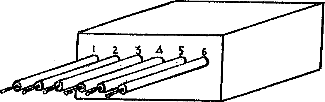
Self-braking electronic module of electric tools
A technology of automatic braking and electronic modules, applied in the direction of motor generator control, electric motor/converter plug, AC motor deceleration device, etc., can solve the problems of complex structure, unsafe, inconvenient, etc., and achieve small size, Low cost and light weight effect
- Summary
- Abstract
- Description
- Claims
- Application Information
AI Technical Summary
Problems solved by technology
Method used
Image

Examples
Embodiment Construction
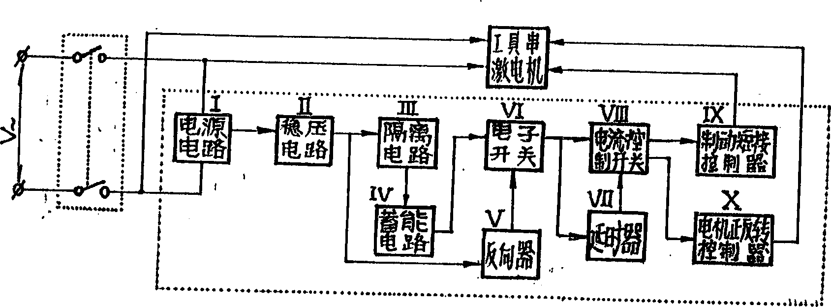
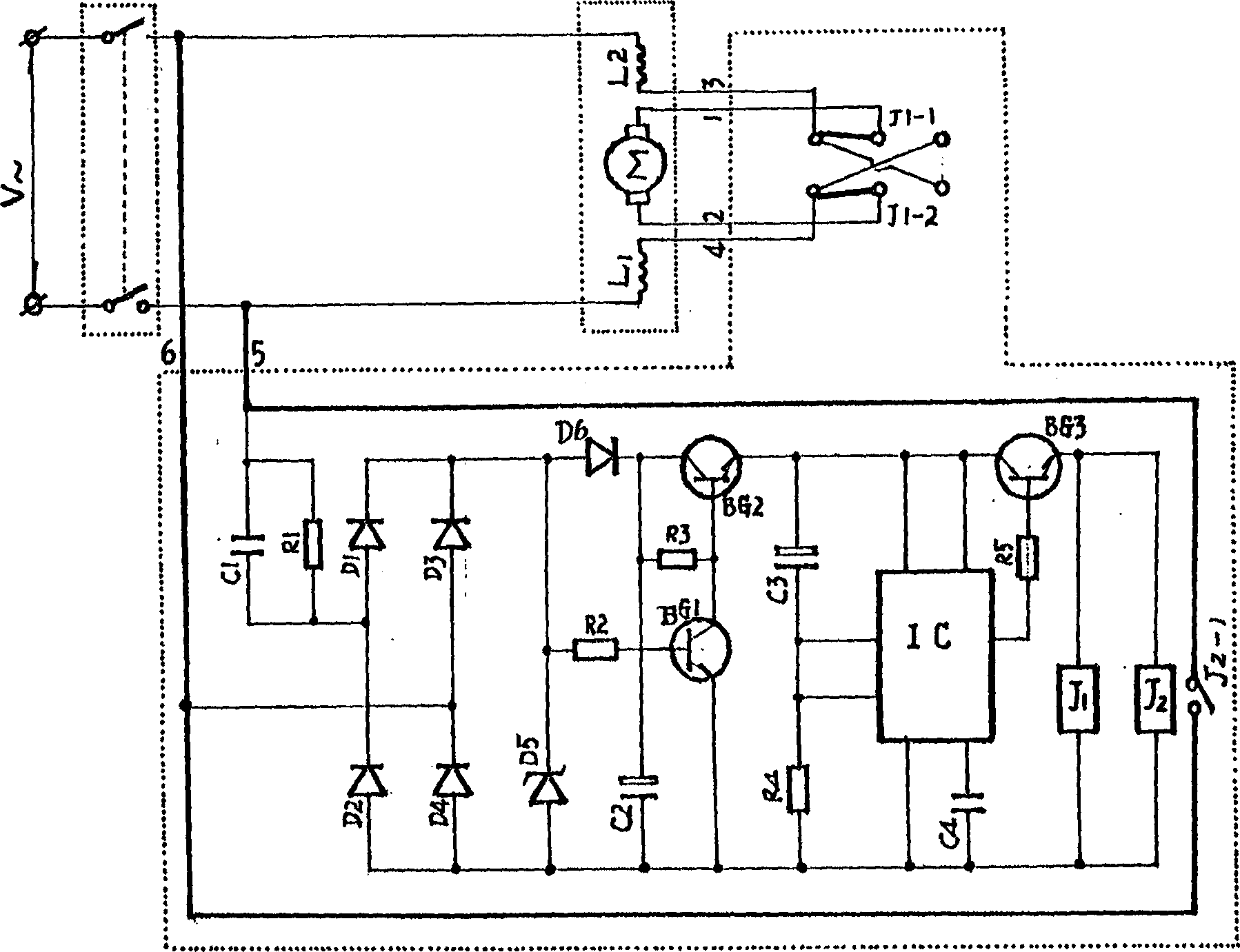
[0009] Now, the present invention will be described in detail in conjunction with the embodiments shown in the accompanying drawings.
[0010] like figure 2 , 3 As shown, the power supply circuit I consists of a step-down capacitor C 1 Parallel resistance R 1 and by the rectifier diode D 1 -D 4 connected into a rectifier consisting of a C 1 , R 1 Connect one end of the parallel branch to the first input of the rectifier, C 1 , R 1 The other end of the parallel connection branch and the other input end of the rectifier are AC power input ends 5 and 6 respectively. The voltage stabilizing circuit II consists of a voltage stabilizing diode D connected in parallel to the output terminal of the rectifier 5 constitute. Isolation circuit III consists of diode D 6 Composition, D 6 Positive connection D 5 negative electrode. The energy storage circuit IV consists of a capacitor C 2 Composition, C 2 Positive connection D 6 Negative pole, negative pole connection D 5 p...
PUM
 Abstract
Description
Claims
Application Information
 - R&D Engineer
- R&D Manager
- IP Professional
- Industry Leading Data Capabilities
- Powerful AI technology
- Patent DNA Extraction
Browse by: Latest US Patents, China's latest patents, Technical Efficacy Thesaurus, Application Domain, Technology Topic, Popular Technical Reports.
© 2024 PatSnap. All rights reserved.Legal|Privacy policy|Modern Slavery Act Transparency Statement|Sitemap|About US| Contact US: help@patsnap.com