Light emitting apparatus

A light-emitting device, solid-state light-emitting technology, applied in the direction of electric solid-state devices, semiconductor devices, electrical components, etc., can solve the problems of blocking reflected light, reducing light radiation efficiency, heat dissipation limitations, etc.

Inactive Publication Date: 2006-12-06
TOYODA GOSEI CO LTD
View PDF1 Cites 4 Cited by
  • Summary
  • Abstract
  • Description
  • Claims
  • Application Information

AI Technical Summary

Problems solved by technology

[0006] However, in the conventional reflective light-emitting device, since the heat generated with the lighting of the LED element is conducted to the outside through the pins to dissipate heat, when the heat generated by the L

Method used


Image

  • Light emitting apparatus
  • Light emitting apparatus
  • Light emitting apparatus

Examples


Embodiment Construction

[0052] Hereinafter, the light emitting device according to the present invention will be described in detail with reference to the drawings.

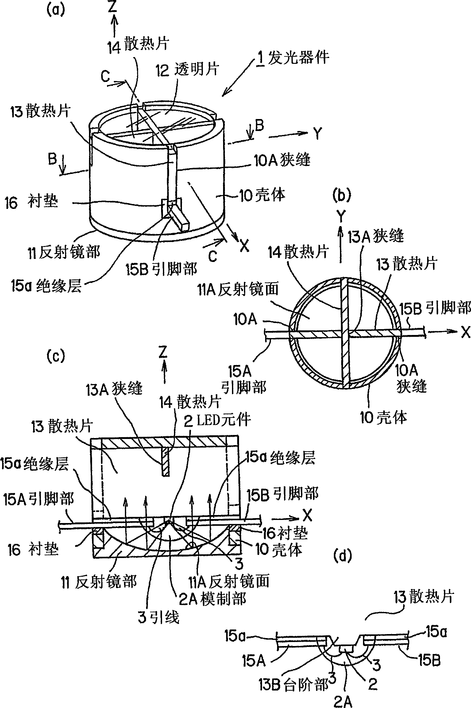
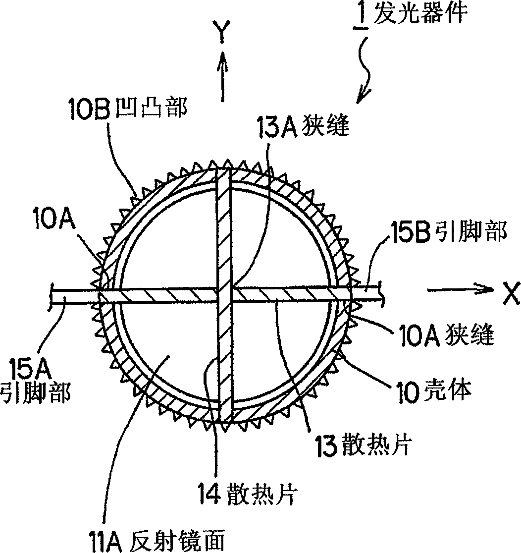
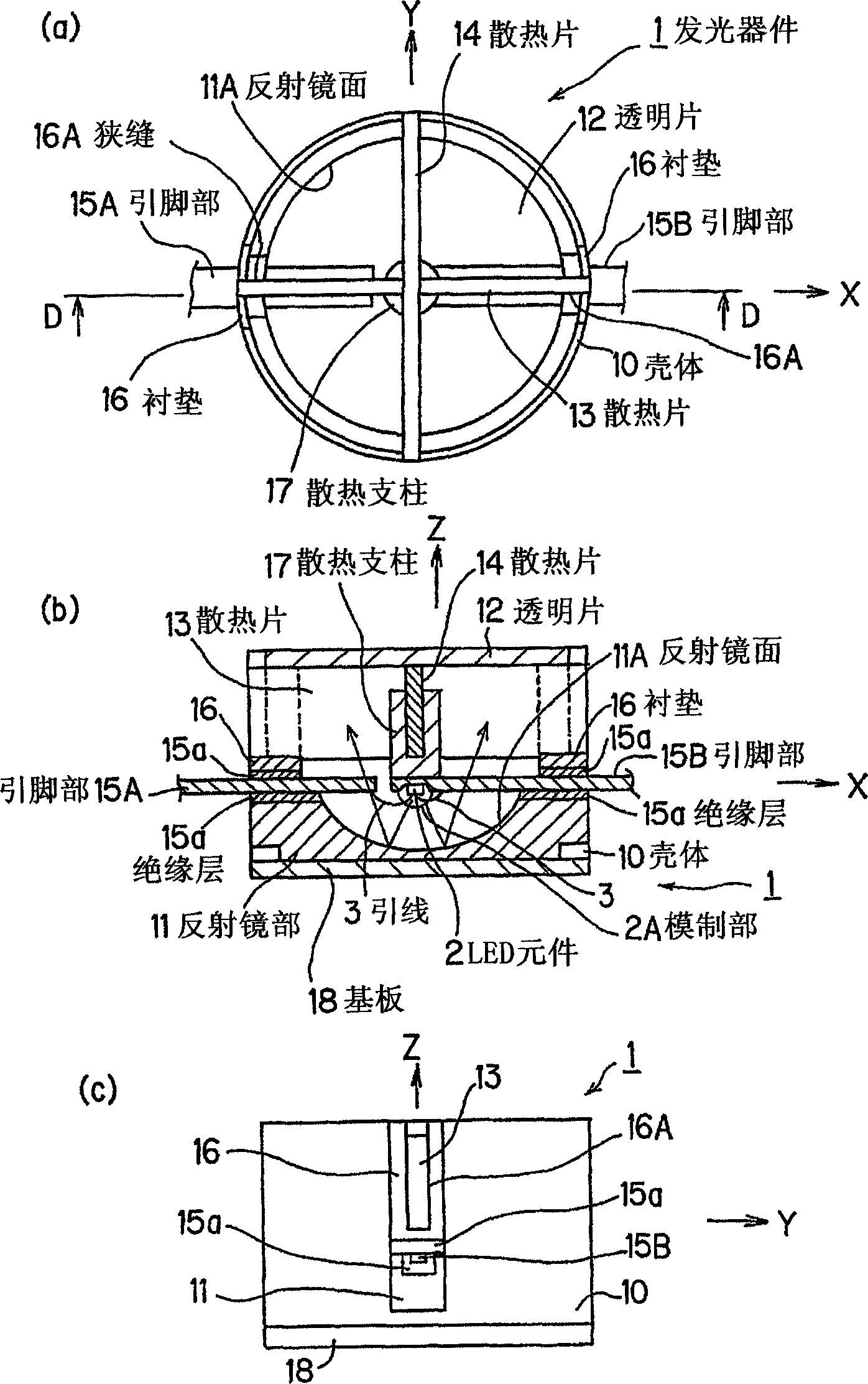
[0053] figure 1(a) is a perspective view, (b) is a transverse sectional view of part B-B in (a), (c) is a longitudinal sectional view of part C-C in (a), (d ) is a partially enlarged view of a modified example of the LED element mounting portion.

[0054] This light-emitting device 1 has: a casing 10, which is formed of a metal material and has good heat dissipation; a reflector portion 11, which is formed to fit the lower part of the casing 10; a transmissive transparent sheet 12, which covers the bottom of the casing 10. Above: heat sinks 13 and 14, which are formed of a metal material with good thermal conductivity, inserted into the inside of the housing 10; LED elements 2, which are mounted on the heat sink 13; lead parts 15A and 15B, which are separated by insulating The layer 15a is fixed on the heat sink 13 as a power supply m...


PUM


Abstract

There is provided a reflectance-type light emitting device having an excellent heat radiation property and capable of using a high-power light emitting element, minimizing the irradiation efficiency lowering of reflected light, and collecting/irradiating a large-output light with a high efficiency. The light emitting device includes: a case (10) made of a metal material and having an excellent heat radiation property; a reflecting mirror unit (11) formed so as to be engaged with the lower portion of the case (10); a light-transparent transparent plate (12) covering the upper surface of the case (10); heat radiation plates (13, 14) made of a metal material having an excellent heat conductivity and inserted into the case (10); an LED element (2) mounted on the heat radiation plate (13); lead portions (15A, 15B) fixed to the heat radiation plate (13) via an insulation layer (15a) so as to serve as power supply members for supplying power to the LED element (2); and a spacer (16) made of an insulating material for insulation between the lead portions (15A, 15B) and the case (10).

Description

technical field [0001] The present invention relates to a light-emitting device, and more particularly, to a reflection-type light-emitting device that reflects light radiated from a light-radiating surface of a light source and radiates it toward the rear side of the light source. Background technique [0002] Conventionally, in Japanese Patent Application Laid-Open No. 5-291627, a reflective light-emitting device has been proposed in which a reflector is arranged opposite to an LED (Light-Emitting Diode: Light-Emitting Diode) element to reflect light radiated from the LED element so that It radiates in the desired direction. [0003] Reflective light-emitting devices, because the LED elements and power supply pins are located on the optical path of reflected light, there is a shortage of partial light being blocked, but because the light radiated from the LED elements can be efficiently concentrated, the light radiation efficiency good. [0004] In recent years, with the...

Claims


Application Information

Patent Timeline
IPC IPC(8): H01L33/00H01L33/48H01L33/64
CPCH01L2224/16225H01L2924/181
Inventor 末广好伸和田聪太田昭人
Owner TOYODA GOSEI CO LTD
Why Eureka
Try Eureka