Dust collection unit of vacuum cleaner

A technology of vacuum cleaners and dust collection devices, applied in the direction of suction filters, etc., can solve problems such as high-frequency noise and user discomfort, and achieve the effect of reducing noise and improving satisfaction

Inactive Publication Date: 2006-12-13
LG ELECTRONICS (TIANJIN) APPLIANCES CO LTD
View PDF0 Cites 76 Cited by
  • Summary
  • Abstract
  • Description
  • Claims
  • Application Information

AI Technical Summary

Problems solved by technology

[0005] Especially when using multiple small cyclonic airflows to remove foreign objects, hi

Method used


Image

  • Dust collection unit of vacuum cleaner
  • Dust collection unit of vacuum cleaner
  • Dust collection unit of vacuum cleaner

Examples


Embodiment Construction

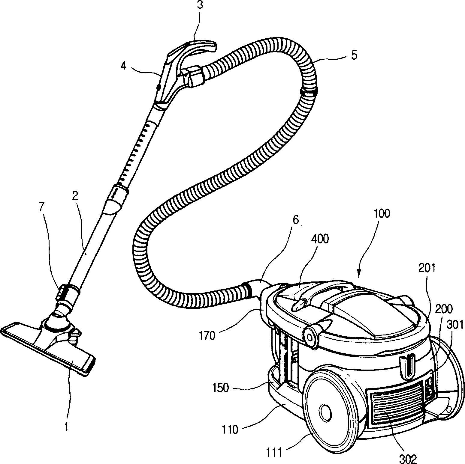
[0027] figure 1 The three-dimensional structure diagram of the vacuum cleaner provided by the present invention.

[0028] Such as figure 1 As shown, the vacuum cleaner provided by the present invention includes a body 100 and a suction pipeline connected to the suction side of the body 100 . The inside of the main body 100 is at least installed with a suction fan and a dust collection device, so that external air can be sucked in and foreign matter can be filtered out and then discharged to the outside.

[0029] The suction pipeline is a pipeline that utilizes the suction inside the vacuum cleaner body 100 to suck air and foreign matter together. Specifically, the suction pipeline includes: a suction nozzle 1 that sucks air mixed with foreign matter from the outside; an extension tube 2 that extends from the suction nozzle 1 and can be stretched according to the use state; 2. The operating handle 3 at the end; the operating part 4 that is arranged on the front portion of th...


PUM


Abstract

The invention discloses a dust collecting device of vacuum cleaner, which comprises the following parts: first separating box with long diameter, second separating box with short diameter to separate the foreign body from the first separating box, commutating part to form at the vent side of second separating box to communicate air flow. The invention can reduce noise in the working course, which improves satisfaction of multi-cyclone flow typed dust collecting device for user.

Description

technical field [0001] The present invention relates to a dust collecting device of a vacuum cleaner, in particular to a dust collecting device of a vacuum cleaner capable of reducing noise generated by a cyclone air flow inside the dust collecting device, thereby improving customer satisfaction. Background technique [0002] A vacuum cleaner is a device that uses the vacuum pressure inside the machine to suck in foreign objects in the air and collect them, thereby cleaning the external environment. The interior of the vacuum cleaner is equipped with a dust collection device that can separate foreign objects in the inhaled air, and the interior of the dust collection device is equipped with a filter device. [0003] The more widely used filter device is made of porous material, so it can pass through the air filter, and when the air flows through the porous material, the foreign matter contained in the air can be separated. However, this kind of filter is not easy to reuse,...

Claims


Application Information

Patent Timeline
IPC IPC(8): A47L9/10
Inventor 金永宗郑会吉黄根裴
Owner LG ELECTRONICS (TIANJIN) APPLIANCES CO LTD
Why Eureka
Try Eureka