Uplink scheduling method for base station control

A scheduling method and base station control technology, applied in the direction of transmission control/balance, communication between multiple stations, etc., can solve problems such as increasing interference from other UEs, wasting downlink transmission power, and reducing wireless resource utilization

Inactive Publication Date: 2006-12-13
HUAWEI TECH CO LTD
View PDF0 Cites 8 Cited by
  • Summary
  • Abstract
  • Description
  • Claims
  • Application Information

AI Technical Summary

Problems solved by technology

[0005] However, in the solution of the prior art, if there are two UEs, one of which is at the edge of the cell and the other is relatively close to the base station, the request rates of the two UEs are the same, and if the resources of the Node B allow Both UEs transmit at the same rate, however, a UE at the cell edge transmitting at the same rate will result in a large transmit power compared to another UE that is closer to the base station, and in a practical wireless environment, It will increase the interference to other UEs and reduce the utilization of wireless resources
[0006] Moreover, in the solution of the prior art, for different UEs, even if it is the same scheduling command, a scheduling command will be sent to each UE separately, which will waste downlink transmission power and reduce the utilization rate of radio resources

Method used


Image

  • Uplink scheduling method for base station control
  • Uplink scheduling method for base station control
  • Uplink scheduling method for base station control

Examples


Embodiment 1

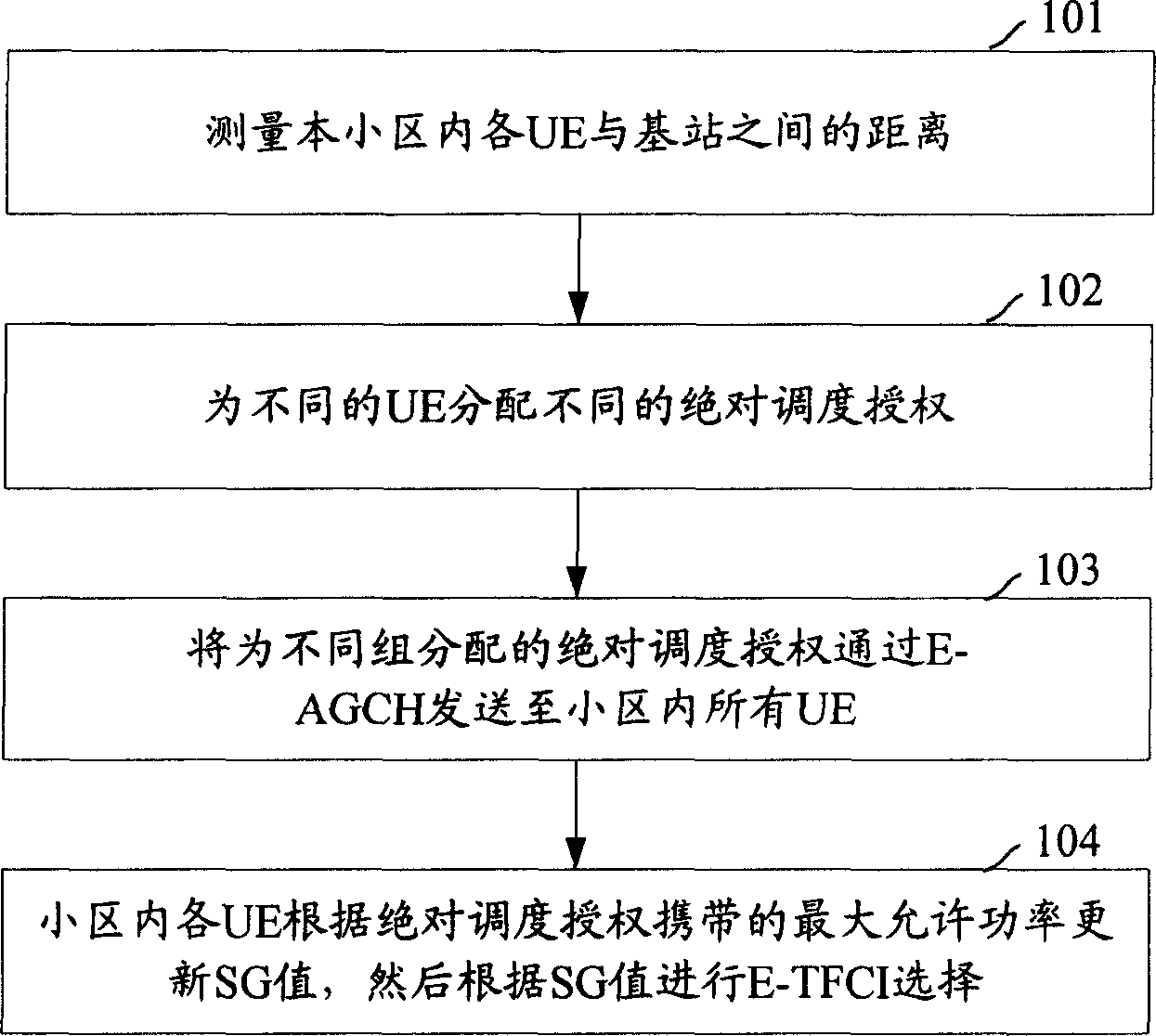
[0043] figure 1 It is a flowchart of uplink scheduling controlled by a base station according to Embodiment 1 of the present invention. Such as figure 1 As shown, in this embodiment, the uplink scheduling controlled by the base station mainly includes the following steps:

[0044] Step 101: Measure the distance between each UE in the cell and the base station.

[0045] The specific measurement method is: measure the path loss of each UE during the scheduling process, and estimate the distance between each UE and the base station according to the path loss.

[0046] In this embodiment, the path loss of each UE in the cell is measured at regular intervals, for example, measured once in several scheduling periods.

[0047] Specifically, the path loss of the UE may be measured in various ways. In this embodiment, the path loss is measured in the following manner:

[0048]The first step is to obtain the maximum transmit power of the UE through the configuration of the Node B o...

Embodiment 2

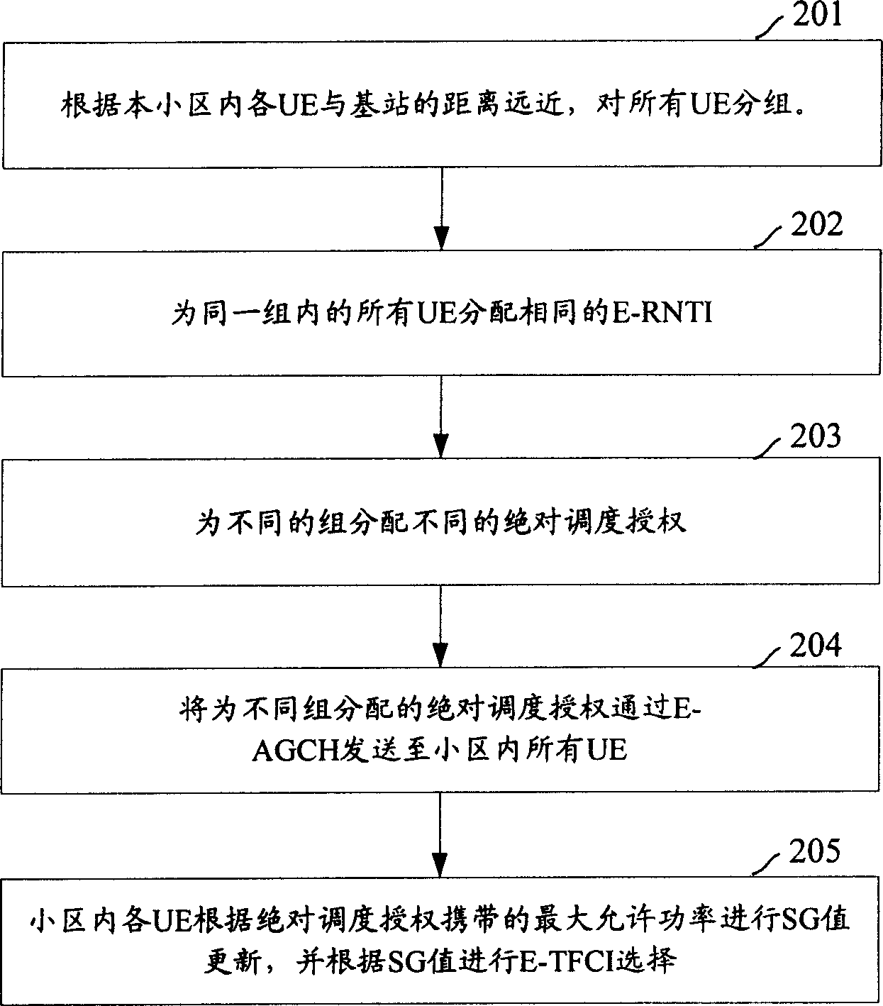
[0060] figure 2 It is a flow chart of uplink scheduling controlled by a base station according to Embodiment 2 of the present invention. Such as figure 2 As shown, in this embodiment, the uplink scheduling controlled by the base station mainly includes the following steps:

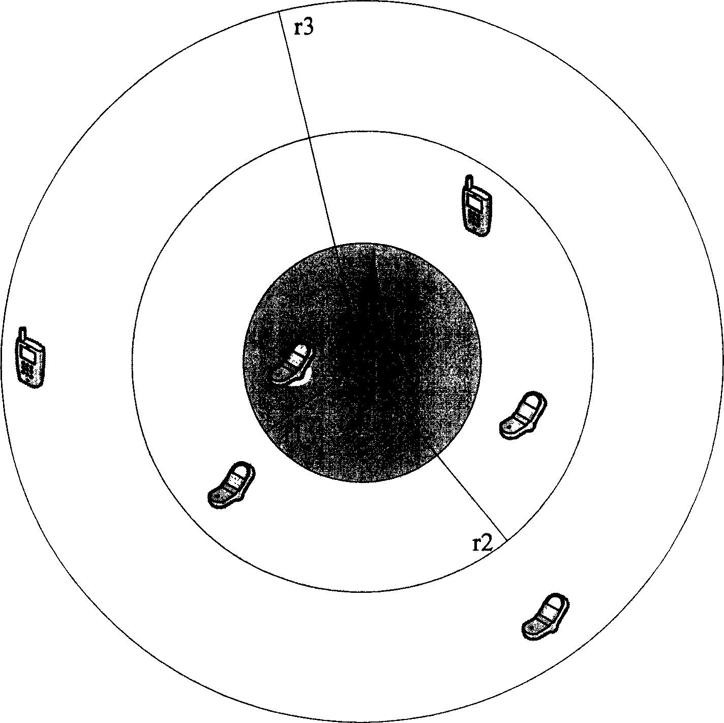
[0061] Step 201: Group all UEs according to the distance between each UE in the cell and the base station.

[0062] The specific grouping strategy is to measure the path loss of each UE during the scheduling process, estimate the distance between each UE and the station according to the path loss, and then group the UEs according to the estimated distance.

[0063] The specific method for measuring the path loss of the UE is the same as the method described in step 101, and will not be repeated here.

[0064] After the path loss of each UE in the cell is obtained, the relative distance between the UE and the base station is estimated according to the path loss, that is, the path loss is converted into...


PUM


Abstract

The invention discloses an ascending dispatching method to control base station, which comprises the following steps: measuring distance between user equipment UE and base station; distributing UE dispatching authorization with higher dispatching authorization for nearer UE to base station and lower dispatching authorization for farther UE from base station. The invention utilizes limit channel resource, which reduces interference for round UE to improve HSUPA system property.

Description

technical field [0001] The present invention relates to High Speed ​​Uplink Packet Access (HSUPA, High Speed ​​Uplink PacketAccess) technology, in particular to an uplink scheduling method controlled by a base station. Background technique [0002] HSUPA technology is a new technology introduced by 3GPP in the Rel'6 protocol to improve the uplink transmission rate. It adopts uplink fast scheduling controlled by Node B, hybrid automatic repeat request (HARQ, Hybrid Automatic Repeat Request), and 2ms short frame technology , so that the user's uplink throughput rate has been greatly improved, theoretically supporting a peak rate of up to 5.76Mbps, and the system's uplink capacity has also been greatly improved, so that multimedia services and packet data transmission can be better developed. [0003] Scheduling data services of user equipment (UE, User Equipment) has always been an important research topic of 3GPP, and uplink scheduling technology is one of the basic problems....

Claims


Application Information

Patent Timeline
IPC IPC(8): H04B7/005H04B7/26
Inventor 姚瑶
Owner HUAWEI TECH CO LTD
Why Eureka
Try Eureka