
Moisture-heat exchanger unit

A technology of heat exchangers and moisture, applied in the direction of gas fuel burners, inhalers, respirators, etc., can solve problems such as complex structures, and achieve the effect of simple equipment, cheap manufacture, and easy operation

Inactive Publication Date: 2006-12-13
HUDSON RESPIRATORY CARE
View PDF3 Cites 13 Cited by
  • Summary
  • Abstract
  • Description
  • Claims
  • Application Information

AI Technical Summary

Problems solved by technology

This is achieved by means of a reciprocating valve arrangement, which leads to a relatively complex construction, which additionally requires valve functions on the inlet and outlet sides

Method used


Image

  • Moisture-heat exchanger unit
  • Moisture-heat exchanger unit
  • Moisture-heat exchanger unit

Examples


Embodiment Construction

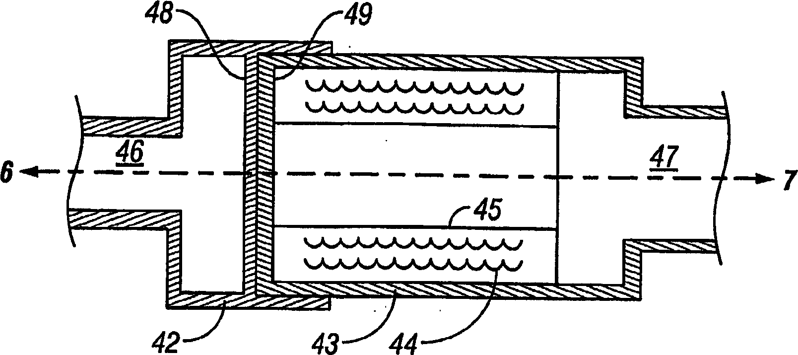
[0038] figure 1 is a schematic diagrammatic longitudinal sectional view according to an embodiment of the present invention. The housing consists of a first part 42 and a second part 43, each of which is connected to the respirator 6 and the patient tube 7 by means of openings 46 and 47, respectively. The housing parts 42 and 43 are rotatable relative to each other, and in the right housing part 43 a filter 44 is arranged. The right housing member 43 is formed as a hollow cylinder having a through hole 45 .

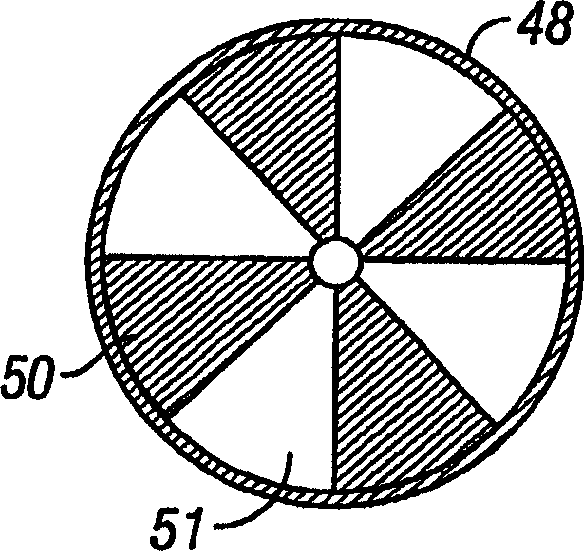
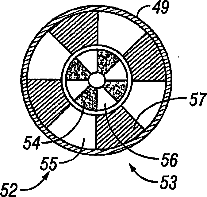
[0039] The first plate 48 is fixedly connected to the housing part 42 and the second plate 49 is fixedly connected to the housing part 43 . Each plate is provided with openings arranged such that, when the plates are in a first rotational position relative to each other, a flow passage through the filter 44 is formed, while flow through the central hole 45 is blocked. In the second rotational position, the opening ends in a position where a flow passage through the cen...


PUM


Abstract

The invention relates to a moisture-heat exchanger unit for tidal air of a patient. The unit comprises a housing (42, 43) arranged for the flowing through of the air. In the housing (42, 43), a filter (44) having the capability of absorbing and desorbing moisture is arranged. According to the invention, there is a rotary valve (48, 49) arranged in the housing (42, 43) for the provision of two alternative flow paths of the air through the housing (42, 43). A first flow path entails that the air flows through the filter (44) and a second flow path entails that the air flows through the housing (42, 43) without flowing through the filter.

Description

technical field [0001] The invention relates to a moisture heat exchanger unit for breathing air of a patient, wherein the unit comprises a housing arranged for air to flow through and a filter arranged in the housing, wherein the filter has a function of absorbing and desorbing moisture. ability. [0002] The invention also relates to the method of operation of such a moisture heat exchanger unit. Background technique [0003] For patients treated with respirators or other similar breathing assistance devices, it has long been known to provide a moisture heat exchanger in the tubing connecting the patient to the respirator. By virtue of the fact that the filter in such a moisture heat exchanger absorbs moisture from the exhaled air and gives it out to the inhaled air, the entrained moisture and heat are brought back to the patient. Therefore, avoid drying of the patient's throat and airway. [0004] However, there are cases where such moisture heat exchangers contain dis...

Claims


Application Information

Patent Timeline
IPC IPC(8): A61M15/00A61M16/00A61M16/10A62B7/00A62B7/10A62B18/08A62B19/00A62B23/02F23D14/00F24J3/00A61MA61M16/20A62B9/00F28C
CPCA61M16/20A62B9/003A61M16/1045
Inventor 汉斯·兰伯特安德斯·威斯尔伯拉德
Owner HUDSON RESPIRATORY CARE
Learn More