Apparatus and method for heat treatment of metallic work pieces

A technology for metal workpieces and workpieces, which is applied in the field of equipment in the form of air furnaces, can solve problems such as impossible heat treatment, and achieve the effect of avoiding oxidation

Inactive Publication Date: 2006-12-13
IPSEN INT INC
View PDF0 Cites 6 Cited by
  • Summary
  • Abstract
  • Description
  • Claims
  • Application Information

AI Technical Summary

Problems solved by technology

However, a completely gas-tight coupling to the quench tank is not possible, so that a completely oxidation-free heat treatment is also not possible when using a bell furnace system

Method used


Image

  • Apparatus and method for heat treatment of metallic work pieces
  • Apparatus and method for heat treatment of metallic work pieces

Examples


Embodiment Construction

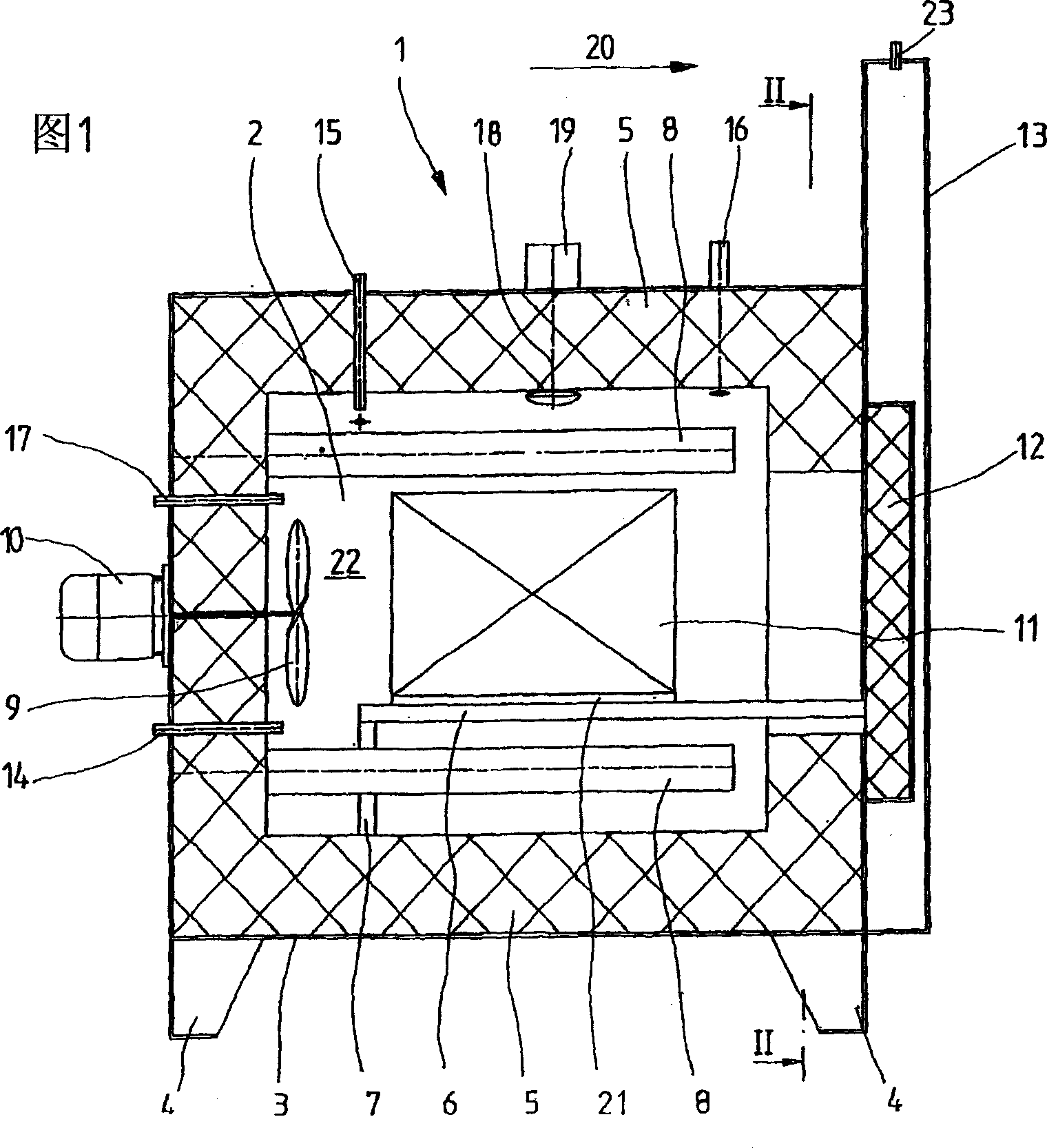
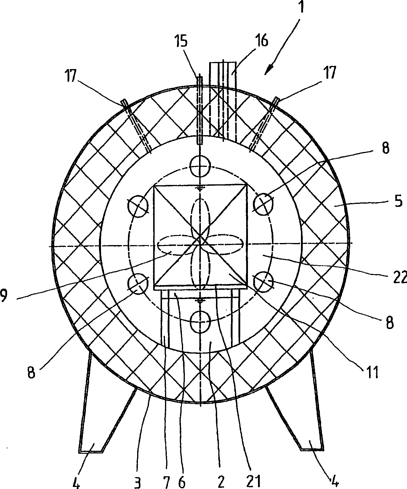
[0063] Figure 1 and figure 2 A furnace according to a preferred embodiment of the invention is shown. This is not limiting and is merely used to illustrate the functionality of the invention. same parts as in Figure 1 and figure 2 are marked with the same reference numerals.

[0064] The furnace 1 consists of a steel housing 3 which has correspondingly formed feet 4 for secure standing. A furnace chamber 2 is formed in a steel casing 3 and has a heat insulating layer 5 provided inside the steel casing 3 for heat insulation.

[0065] In order to circulate the air in the oven chamber, a gas circulation device in the form of a ventilation device 9 is provided in the oven chamber 2 . The ventilation device 9 is driven by a motor 10 which is accessible from the outside and is arranged outside the oven chamber 2 . In terms of drive technology, the motor 10 and the ventilation device 9 are connected via a drive shaft which is not described in detail.

[0066] The heating elemen...


PUM


Abstract

The invention relates to a horizontal atmospheric furnace for heat treating, in particular, metallic workpieces at high temperatures. In order to create a furnace that, while having a simple design and being easy to operate at the same time, enables a transfer of heat-treated workpieces into a quenching device while concluding the atmosphere surrounding the furnace, the invention provides that a horizontal atmospheric furnace for heat treating, in particular, metallic work pieces (11) at high temperatures with a preferably cylindrical furnace chamber (2) and with a furnace door (12) that closes the furnace chamber (2) in a gas-tight manner. Said furnace door (12) is mounted in a manner that enables it to be displaced inside a door case (13), which forms a lock that can be closed in a gas-tight manner.

Description

technical field [0001] The invention relates to an apparatus in the form of an air furnace for the heat treatment at high temperatures, in particular of metal workpieces. The invention also relates to a method for the heat treatment, in particular of metal workpieces, in such a furnace. Background technique [0002] Furnaces of the aforementioned type have hitherto been used in a vertical configuration as so-called shaft furnaces. However, the shortcoming of the shaft furnace is that after the heat treatment of the metal workpieces, these workpieces must be lifted out of the shaft furnace by means of a spreader and transported to the quenching tank arranged next to the shaft furnace. During this transfer process, contact of the heat-treated workpiece with ambient gas disadvantageously leads to oxidation of the heat-treated workpiece, with consequent consequences of surface decarburization and consequent loss of mass. [0003] In order to overcome the above-mentioned disadv...

Claims


Application Information

Patent Timeline
Patent Type & Authority Applications(China)
IPC IPC(8): C21D1/74F27B17/00F27D3/00F27D3/12F27D7/04F27D7/06F27D19/00F27D99/00
CPCF27D2099/008F27D2003/0091F27D7/04F27B17/0083F27D2007/063F27D2007/045F27D2019/0012F27D2003/124F27D19/00
Inventor 贝恩德·埃登霍费尔托马斯·帕里亚斯
Owner IPSEN INT INC
Why Eureka
Try Eureka