

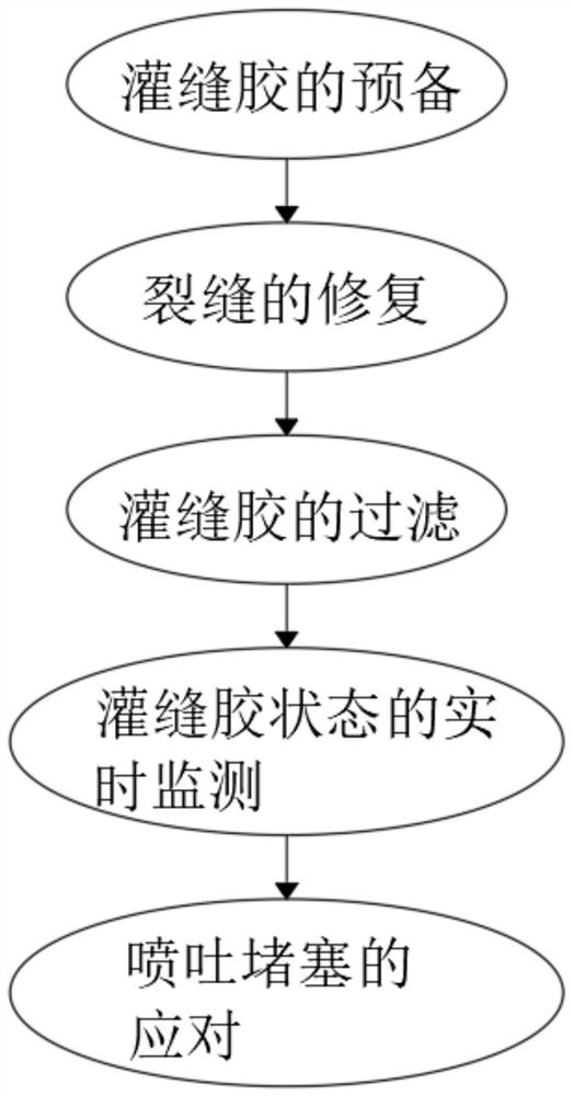
Road maintenance crack pouring construction process
A construction technology and highway maintenance technology, applied in the direction of roads, roads, road repair, etc., can solve the problems of uneven temperature distribution, prone to local heating, unable to fill seam glue, impurity isolation, etc., to improve the anti-clogging effect and avoid local problems. Heat, avoid condensation effect
- Summary
- Abstract
- Description
- Claims
- Application Information
AI Technical Summary
Problems solved by technology
Method used
Image

Examples
Embodiment 1
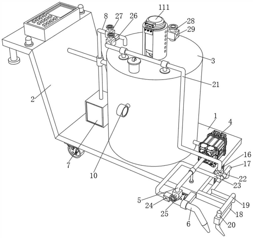
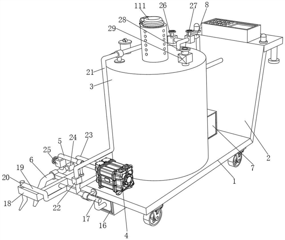
[0037] see Figure 2 to Figure 8 , the seam filling device includes a support panel 1 , and a support frame 2 is fixed on one side of the support panel 1 . The support frame 2 is provided with a control box, which is convenient for controlling the electrical components in the device. The support panel 1 is provided with a heater 7, a placing tank 3 and a gear pump 4 sequentially from left to right. The design of the heater 7 is convenient to provide a heating source for the placement tank 3 , and a disc 12 is fixed on the top of the inner cavity of the placement tank 3 . The outlet end of the heater 7 is communicated with an outlet pipe 8 , and the end of the outlet pipe 8 away from the heater 7 penetrates into the placing tank 3 . The outlet pipe 8 is connected with an elbow 9 and the elbow 9 is located in the placing tank 3 , and one end of the elbow 9 away from the outlet pipe 8 penetrates the disk 12 and extends downward.
[0038] The placement tank 3 is provided with an...
Embodiment 2
[0041] see Figure 2-8 , the seam filling device includes a support panel 1 , and a support frame 2 is fixed on one side of the support panel 1 . The support frame 2 is provided with a control box, which is convenient for controlling the electrical components in the device. The support panel 1 is provided with a heater 7, a placing tank 3 and a gear pump 4 in sequence from left to right. The design of the heater 7 is convenient for A heating source is provided inside the tank 3. A disc 12 is fixed on the top of the inner cavity of the placement tank 3 , and an outlet pipe 8 is connected to the outlet end of the heater 7 , and the end of the outlet pipe 8 away from the heater 7 penetrates into the placement tank 3 . The outlet pipe 8 is connected with an elbow 9, the elbow 9 is located in the placing tank 3, and one end of the elbow 9 away from the outlet pipe 8 penetrates the disk 12 and extends downward.
[0042] The placement tank 3 is provided with an auxiliary mechanism ...
PUM
 Abstract
Description
Claims
Application Information