Clip for office

A technology using clips and main bodies, applied in printing, binding and other directions, to achieve the effect of reducing the number of manufacturing processes, easy disassembly, and lowering purchase costs

Inactive Publication Date: 2006-12-20
金荣熙
View PDF1 Cites 4 Cited by
  • Summary
  • Abstract
  • Description
  • Claims
  • Application Information

AI Technical Summary

Problems solved by technology

[0009] In order to fix the handle 5, all the clips of the prior art have the left and right side cylindrical parts 3a, 3b, but if the office clips with such cylindrical parts 3a, 3b are used to bind the largest amount of documents, then as Image 6 As shown, the two surfaces of the clip main body 1 are almost horizontal, so the cylindrical parts 3a, 3b protrude to a position higher than the two surfaces of the clip main body 1

Method used


Image

  • Clip for office
  • Clip for office
  • Clip for office

Examples


Embodiment Construction

[0032] Hereinafter, embodiments of the present invention will be described with reference to the drawings.

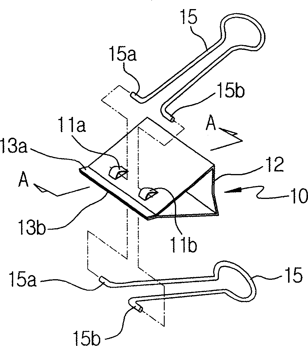
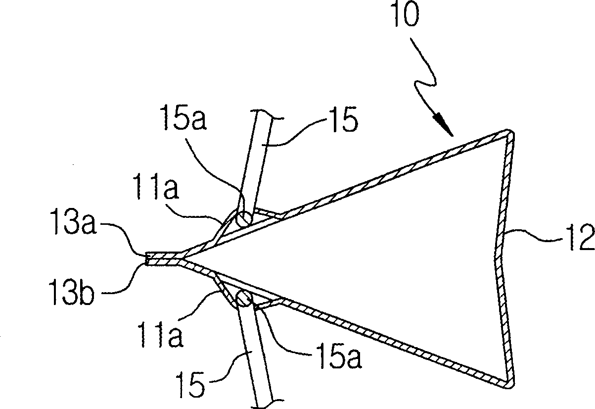
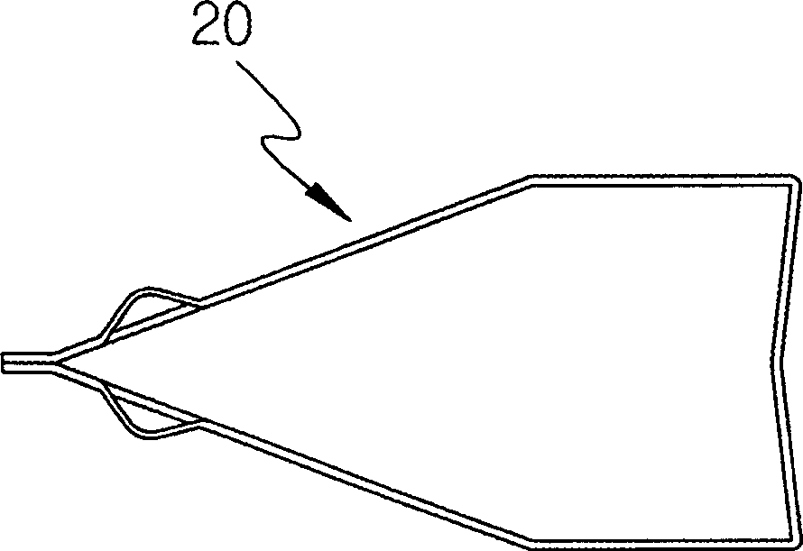
[0033] figure 1 It is a perspective view of the office clip of the present invention, figure 2 for along figure 1 A cross-sectional view of line A-A is shown, image 3 It is a side view of other embodiments of the office clip of the present invention, Figure 4 It is the use status diagram of the office clip of the present invention.

[0034] First of all, in the office clip of the present invention, as figure 1 As shown, the clip body 10 is bent around the center, and its two ends are in elastic contact with each other. In the clip body, the closer the two ends are to the bent portion 12 , the greater the distance difference is. In addition, the main body 10 is preferably made of the same high-carbon steel sheet as in the prior art.

[0035] And, if figure 2 As shown, the cross-section of the main body 10 is roughly formed as an isosceles triangle, but as s...


PUM


Abstract

The invention provides a clip for office use, which comprises a main body made of sheet material, a bended portion with a center, two pairs of hook-like cramping grooves, two outward projections, a pair of handles and a pair of inserted protrusions.

Description

technical field [0001] The present invention relates to an office clip, and more specifically, to an office clip capable of improving productivity by reducing the overall material of the clip body, reducing manufacturing costs and reducing the number of manufacturing steps. Moreover, the office clip not only can accommodate and store documents easily, but also has a handle that can be easily disassembled, thereby improving the convenience in use. Background technique [0002] Such as Figure 5 As shown, the existing office clip includes a clip body 1 whose cross section is roughly an isosceles triangle. The front end of the clip body 1 is in contact with the elastic force of the clip body 1 itself for holding documents. [0003] At the front end of the main body 1, left and right cylindrical portions 3a, 3b into which insertion protrusions 5a, 5b formed at both ends of the handle 5 are inserted are formed. Protrusions 3c are formed between the left and right cylindrical pa...

Claims


Application Information

Patent Timeline
IPC IPC(8): B42F1/02
CPCB42F1/006B42F1/02
Inventor 金荣熙
Owner 金荣熙
Why Eureka
Try Eureka