Shock absorber

A shock absorber and vehicle technology, applied in the direction of shock absorber, shock absorber, spring/shock absorber, etc., can solve the problem that the shock absorber cannot cope with large damping force

Active Publication Date: 2006-12-20
KYB CORP
View PDF4 Cites 30 Cited by
  • Summary
  • Abstract
  • Description
  • Claims
  • Application Information

AI Technical Summary

Problems solved by technology

However, shock absorbers that generate damping force in response to amplitude cannot cope with, for example, situations that require a large damping force relative to input vibrations with small amplitudes.

Method used


Image

  • Shock absorber
  • Shock absorber
  • Shock absorber

Examples


Embodiment Construction

[0027] The embodiments of the invention in which exclusive rights or privileges are claimed are defined as follows.

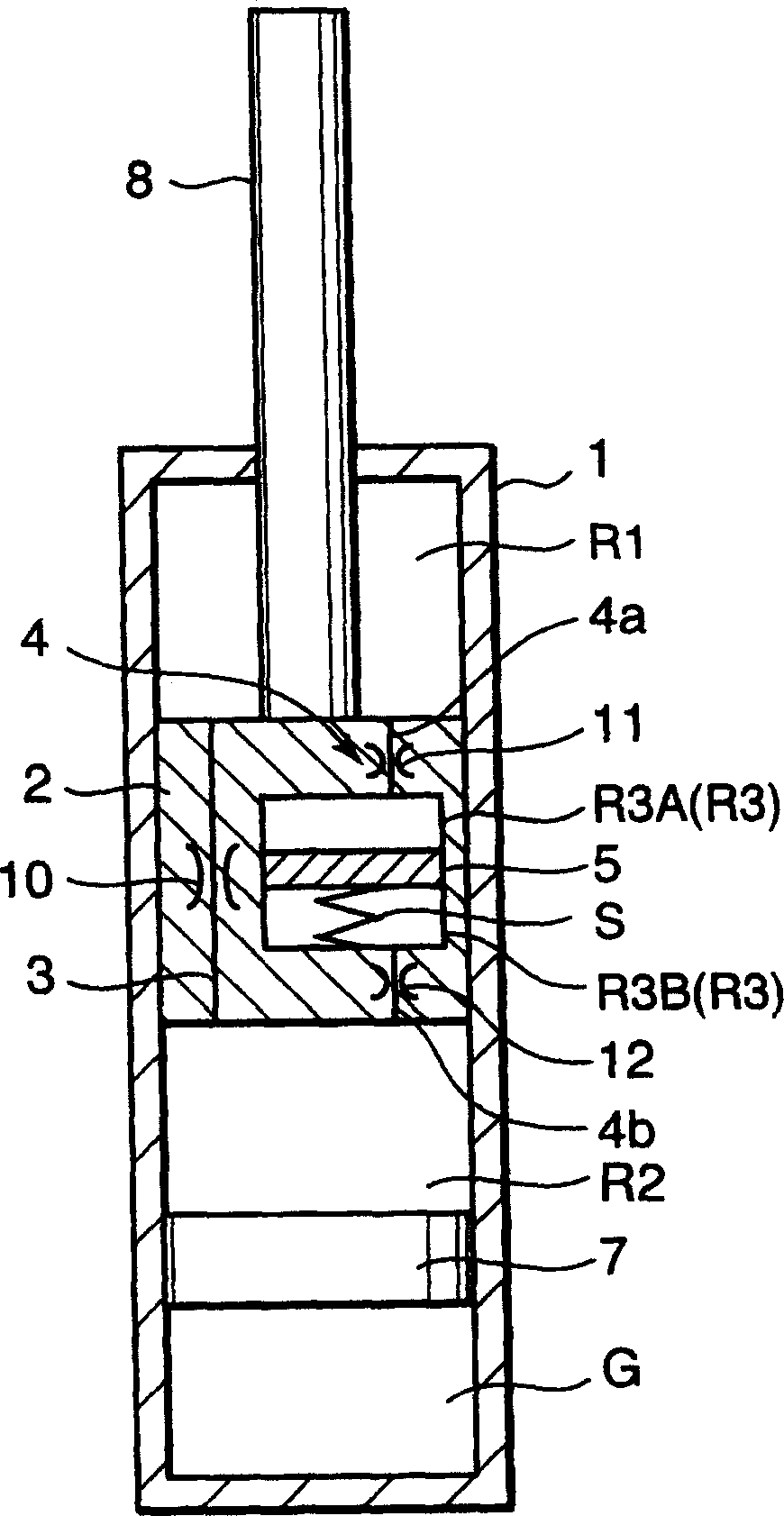
[0028] Refer to the attached figure 1 , the shock absorber for vehicles includes a cylinder 1, a main piston 2 that slides in the cylinder 1 and divides the cylinder 1 into two working chambers, and protrudes from the cylinder 1 and is connected to the main piston 2 The piston rod 8. The two working chambers are designed as an upper working chamber R1 above the main piston 2 and a lower working chamber R2 below the main piston 2 .

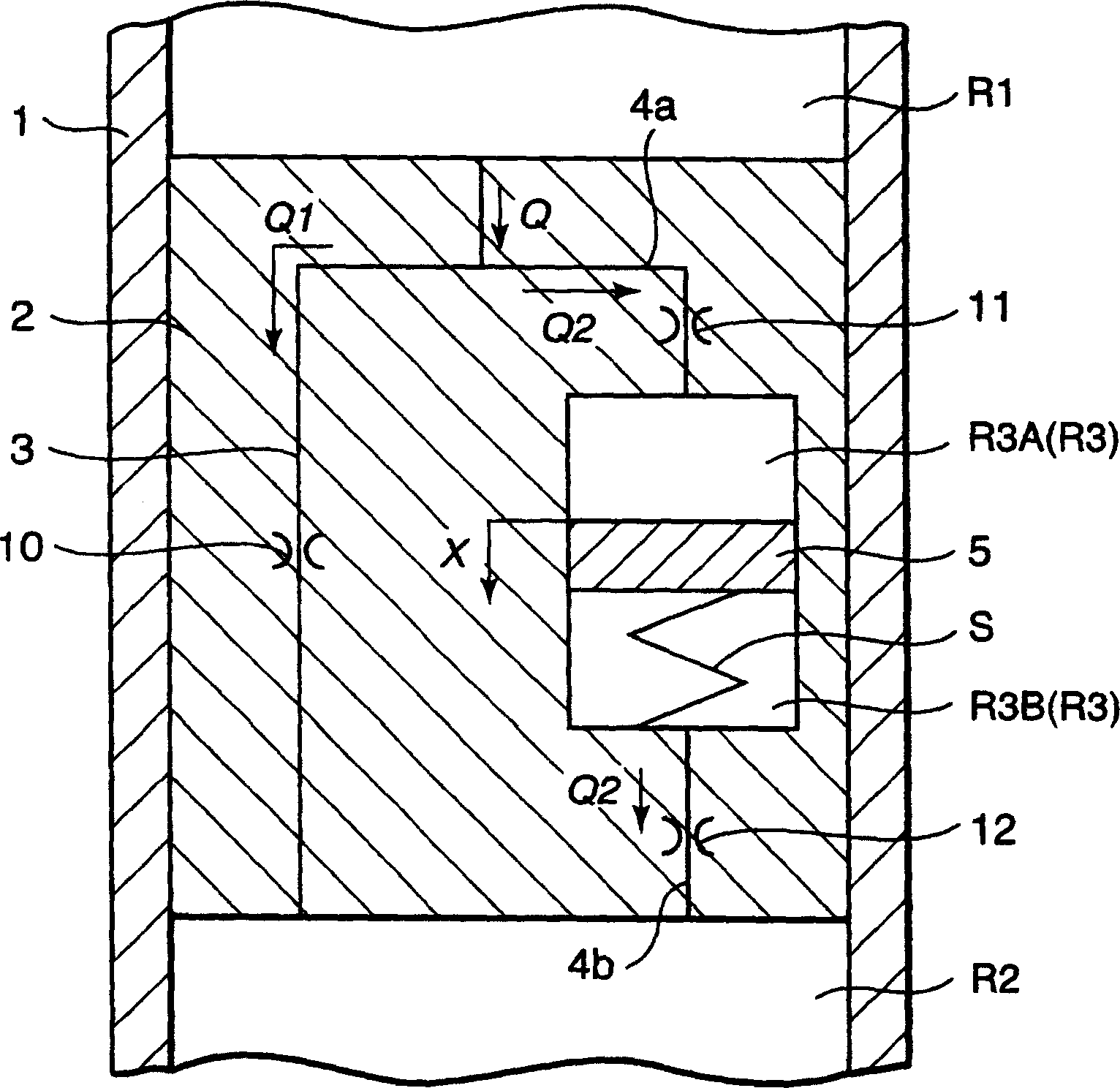
[0029] The upper working chamber R1 and the lower working chamber R2 communicate through the first channel 3 provided in the main piston 2 .

[0030] A cylindrical pressure chamber R3 is provided in the main piston 2 and the free piston 5 is accommodated therein. The pressure chamber R3 is divided into an upper pressure chamber R3A and a lower pressure chamber R3B by the free piston 5 . The working oil fills the upper working ch...


PUM


Abstract

A shock absorber interposed in parallel with a suspension spring between a vehicle wheel and a vehicle body of a vehicle comprises a main piston (2) partitioning a cylinder (1) into a first operating chamber (R1) and a second operating chamber (R2), and connected to a piston rod (8). The first operating chamber (R1) and the second operating chamber (R2) are connected by a laminated leaf valve (V1, V2) under a first flow resistance. A passage (4a) connects one of the pressure chambers (R3A, R3B) partitioned by a free piston (5) and the first operating chamber (R1) under a second flow resistance. A passage (4b) connects the other of the pressure chambers (R3A, R3B) and the second operating chamber (R2) under a third flow resistance. The shock absorber displays stable damping force characteristics as a result of a spring (S) supporting the free piston (5) in a predetermined neutral position.

Description

technical field [0001] The invention relates to a shock absorber for a vehicle. Background technique [0002] US2005 / 0011712A1 published by the United States Patent and Trademark Office in 2005, JPH07 / 019642U1 published by the Japan Patent Office in 1995, and JP2000-356237A1 published by the Japan Patent Office in 2000 disclose a shock absorber respectively. Each of these shock absorbers consists of a cylinder, a main piston that divides the cylinder into two working chambers, a channel disposed within the main piston and connecting the two working chambers, and a Two connected pressure chambers. [0003] These shock absorbers produce relatively small damping forces due to the small vibrations of the working oil moving between the pressure chamber and the working chamber in response to the displacement of the free piston. On the contrary, a large vibration causes the free piston to move to the end of the stroke, so that the working oil cannot move between each working cham...

Claims


Application Information

Patent Timeline
Patent Type & Authority Applications(China)
IPC IPC(8): F16F9/34F16F9/50
Inventor 寺冈崇志政村辰也吉田太志
Owner KYB CORP
Why Eureka
Try Eureka