Method for load limitation in drive systems for a high lift system for aeroplanes

A driving system and load technology, which is applied to indicate the direction of the aircraft's movable elements, aircraft parts, aircraft indicating devices, etc., and can solve the problems of increased mass, operating costs, and complex structures of the aircraft

Inactive Publication Date: 2006-12-20
AIRBUS OPERATIONS GMBH
View PDF0 Cites 26 Cited by
  • Summary
  • Abstract
  • Description
  • Claims
  • Application Information

AI Technical Summary

Problems solved by technology

However, due to the complex construction of such systems, aircraft equipped with them increase the mass and operating costs, moreover, due to their functionality, they are activated only in the event of an error
In the case of very tight design tolerances and system dynamics that are very sensitive to parameters, such load limiting devices eventually also react in aperiodically but error-free drive systems and prevent the entire system from operating

Method used


Image

  • Method for load limitation in drive systems for a high lift system for aeroplanes
  • Method for load limitation in drive systems for a high lift system for aeroplanes
  • Method for load limitation in drive systems for a high lift system for aeroplanes

Examples


Embodiment Construction

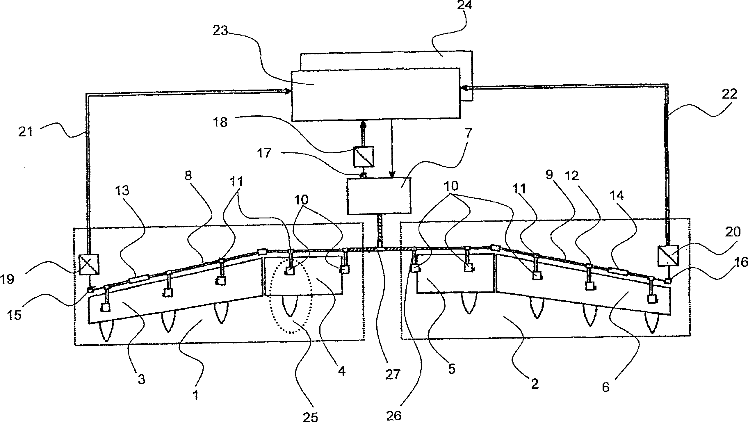
[0012] figure 1 The landing flap actuation system shown is equipped with an electronically adjustable overload protector instead of a conventional mechanical load limiter. Here, the drive system comprises left and right wing subsystems 1, 2, which are respectively used to drive two high-lift flaps 3, 4 and 5, 6, which are arranged on the rear edge of the wing. The structures of the two subsystems 1 and 2 here are symmetrical to each other. The mechanical power necessary to position the flaps 3 to 6 is provided by the central drive unit 7 and transmitted to a series of mechanical actuators 10 in the two wings via drive chains 8, 9, respectively, wherein the central drive unit 7 Power can be controlled in a highly dynamic manner.

[0013] They each also include branch transmissions 11 , 12 . Each drive station 25 is connected to the drive chain 8 through its respectively configured branch transmission mechanism 11 . Furthermore, hydraulically actuated brakes 13 , 14 are arra...


PUM


Abstract

The invention relates to a device for load limitation in a high lift system for aeroplanes, said system comprising individual segments (3, 4, 5, 6) of landing flap systems and slat flap systems, and a drive unit (7). The inventive device for load limitation comprises a control unit (23) that is connected to position sensors (15, 16, 17) and is embodied in such a way as to process signals from the position sensors and to generate a signal for limiting the supplied drive power. The invention also relates to a method for load limitation. According to said method, signals from at least two position sensors are measured; at least one reference variable is calculated from the measured signals; each reference variable is compared with a corresponding threshold value pre-determined from a maximum authorised load; and a control signal is generated for limiting the drive power, when at least one of the reference variables reaches or exceeds the threshold value.

Description

technical field [0001] The invention relates to a load limiting method and device in an aircraft high-lift system, wherein the aircraft high-lift system has a branch drive system to transmit mechanical power to the drive stations of each section of the landing flap and / or leading edge slat system, and has Position sensor and drive unit. Background technique [0002] Aircraft high-lift systems are known having a central drive unit and branch drive systems providing mechanical power to the drive stations of the various segments of the landing flap / slat system. If the transmission of a landing flap segment and / or branch drive system is blocked, this segment and the corresponding branch of the drive system and / or the transmission mechanism and the corresponding drive system branch must absorb the full drive energy of the drive unit as a reaction moments and must therefore be constructed as thick and heavy members. [0003] As a protective device, in this high-lift aircraft sys...

Claims


Application Information

Patent Timeline
Patent Type & Authority Applications(China)
IPC IPC(8): B64D45/00
CPCB64D2045/001B64D45/0005
Inventor U·卡尔U·诺伊曼B·霍勒特
Owner AIRBUS OPERATIONS GMBH
Why Eureka
Try Eureka