Smoke sensor using scattering light

A smoke sensor and light scattering technology, which is applied to instruments, alarms, fire alarms, etc., to reduce maintenance costs and improve design quality

Inactive Publication Date: 2006-12-20
HOCHIKI CORP
View PDF2 Cites 33 Cited by
  • Summary
  • Abstract
  • Description
  • Claims
  • Application Information

AI Technical Summary

Problems solved by technology

[0007] For existing light-scattering smoke sensors, the smoke chamber is actually a necessary structure that is prone to problems

Method used


Image

  • Smoke sensor using scattering light
  • Smoke sensor using scattering light
  • Smoke sensor using scattering light

Examples


Embodiment Construction

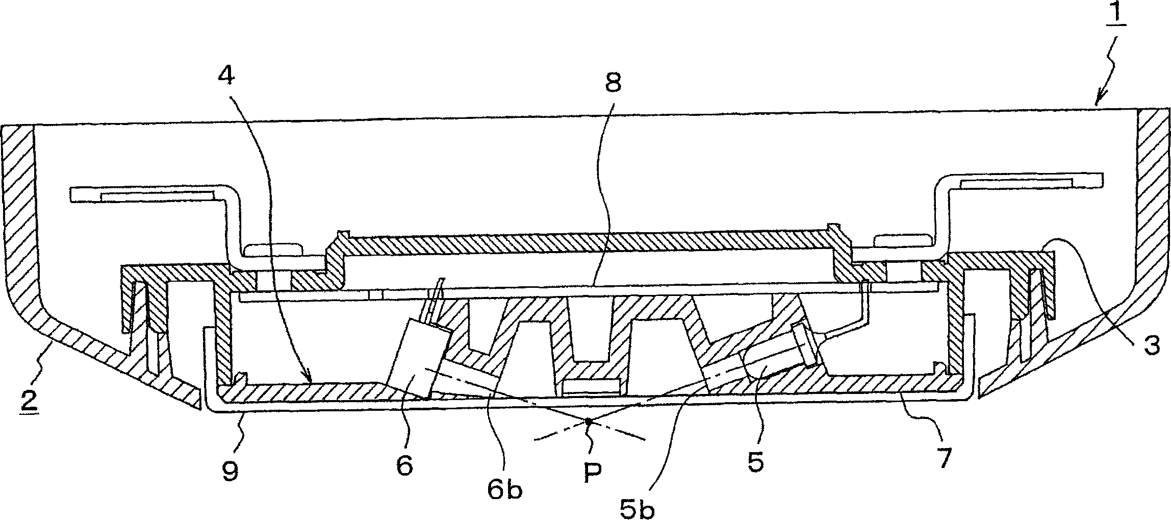
[0121] First, the light scattering type smoke sensor in the first embodiment will be described. figure 1 is a sectional view of the light scattering type smoke sensor in the first embodiment of the present invention. like figure 1 As shown, the light scattering smoke sensor 1 includes a sensor body 2 , a terminal plate 3 , a cavity base 4 , a light emitter 5 , a light receiver 6 and a transparent cover 9 .

[0122] The terminal board 3 is arranged inside the sensor main body 2 , and the circuit board 8 is arranged inside the terminal board 3 . The cavity base 4 is located at the lower part of the circuit board 8, and the light emitter 5 is disposed inside the cavity base 4, the light emitter 5 serves as an optical signal transmitter, and the light receiver 6 serves as an optical signal receiver.

[0123] The outer surface 7 of the sensor body 2 is a lower surface of the cavity base 4 and is substantially a plane, and the transparent cover 9 is attached to the outer surface 7...


PUM


Abstract

A smoke sensor using scattering light comprises a sensor body, light-emitting means for emitting light toward an open smoke-sensing space present outside the sensor body, light-receiving means for receiving scattering light of the light emitted toward the smoke sensing space and outputting a light-reception signal according to the amount of scattering light received, and a fire judging means for judging whether fire occurs or not on the basis of the amount of received light determined on the basis of the outputted light-reception signal.

Description

technical field [0001] The present invention relates to a light scattering type smoke sensor which senses smoke by emitting light and detecting the light scattered by the smoke. Background technique [0002] Existing light-scattering smoke sensors mainly include a smoke cavity through which smoke enters the sensor from the outside. An inner space of the smoke cavity is used as a smoke sensing space, the light emitted by a light emitting element arranged in this space is scattered by the smoke, and the scattered light is received by a light receiving element, thereby detecting the occurrence of a fire. [0003] The smoke sensing space is set in the smoke cavity of the smoke sensor to accurately sense weak scattered light generated by the smoke without being disturbed by external light, and at the same time prevent foreign objects from entering the smoke sensing space. However, if a foreign object such as a small insect enters into the smoke sensing space, it may cause scatte...

Claims


Application Information

Patent Timeline
Patent Type & Authority Applications(China)
IPC IPC(8): G08B17/107
Inventor 长岛哲也
Owner HOCHIKI CORP
Why Eureka
Try Eureka