Heating device
A heating device and electromagnetic induction heating technology, applied in induction heating device, electric heating device, induction heating and other directions, can solve the problems of leakage, decrease of magnetic permeability of heating layer, increase of heating temperature of heating components, etc., to ensure safety, reduce Assembly man-hours and the effect of reducing the number of components
- Summary
- Abstract
- Description
- Claims
- Application Information
AI Technical Summary
Problems solved by technology
Method used
Image

Examples
Embodiment approach 1
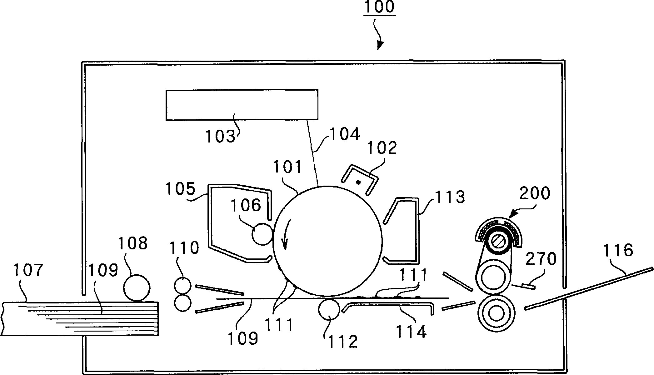
[0036] figure 1 It is a schematic cross-sectional view showing the overall configuration of an image generating device using the heating device according to Embodiment 1 of the present invention as a fixing device for heating and fixing an unfixed image on a recording medium.
[0037] Such as figure 1As shown, an image generating device 100 has an electrophotographic photosensitive element (hereinafter, referred to as a "photosensitive drum") 101, a charger 102, a laser beam scanner 103, a developing device 105, a paper feeding device 107, a fixing device 200, and a cleaning device. device 113 etc.
[0038] exist figure 1 Here, while the photosensitive drum 101 is rotationally driven in the direction of the arrow at a predetermined peripheral speed, its surface is uniformly charged at a negative predetermined dark potential VO by the charger 102 .
[0039] Laser beam scanner 103, the output is based on an image reading device not shown in the figure or a host such as a comp...
Embodiment approach 2
[0082] Next, the structure of the characteristic part of the heating apparatus concerning Embodiment 2 of this invention is demonstrated. Image 6 It is a schematic side view showing the structure of the heating device according to the second embodiment. Figure 7 represents the heating device according to Embodiment 2 Image 6 The B-B sectional view in . Such as Image 6 and Figure 7 As shown, the configuration of the heating device 600 according to the second embodiment is to operate the thermostat 301 by heat conduction of the flat heat conduction element 601 , and the other configurations are the same as those of the heating device 300 according to the first embodiment.
[0083] Here, the heat conduction element 601 is arranged between the wires of the excitation coil 231 with its plane along the turn direction of the wire of the excitation coil 231 , and the thermostat 301 is arranged on the side of the extended portion of the heat conduction element 601 .
[0084] T...
Embodiment approach 3
[0087] Next, the structure of the characteristic part of the heating apparatus concerning Embodiment 3 is demonstrated. Figure 8 It is a schematic plan view showing the structure of the heating device according to Embodiment 3. Figure 9 represents the heating device according to Embodiment 3 of the present invention Figure 8 The C-C sectional view in, Figure 10 It is a graph showing the calorific value of the heating device according to Embodiment 3 of the present invention.
[0088] Such as Figure 8 and Figure 9 As shown, in the heater 800, the thermostat 301 is arranged at the side end of the wire bundle of the exciting coil 231, sandwiched between the exciting coil 231 and the central core 232b, and other structures are related to the first embodiment The heating device 300 is the same.
[0089] In this heater 800, since the thermostat 301 is already provided at the side end of the wire bundle of the exciting coil 231, when the thermostat 301 is installed, it is ...
PUM
 Abstract
Description
Claims
Application Information
 - R&D
- Intellectual Property
- Life Sciences
- Materials
- Tech Scout
- Unparalleled Data Quality
- Higher Quality Content
- 60% Fewer Hallucinations
Browse by: Latest US Patents, China's latest patents, Technical Efficacy Thesaurus, Application Domain, Technology Topic, Popular Technical Reports.
© 2025 PatSnap. All rights reserved.Legal|Privacy policy|Modern Slavery Act Transparency Statement|Sitemap|About US| Contact US: help@patsnap.com