Equipment topology structure forming method in stack system

A stacking system and topology technology, applied in the network field, can solve problems such as UNIT4 misunderstanding, and achieve the effect of solving abnormal problems, improving service quality, and improving stability

Active Publication Date: 2006-12-27
NEW H3C TECH CO LTD
View PDF0 Cites 16 Cited by
  • Summary
  • Abstract
  • Description
  • Claims
  • Application Information

AI Technical Summary

Problems solved by technology

However, since the MAC addresses of UNIT 1 and UNIT 4 are exactly the same, the Ad packet sent by UNIT1 is the same as the Ad packet sent by UNIT 4, which will make UNIT4 mistakenly believe that it has received the Ad packet sent by itself, and then think that the topology is a ring;

Method used


Image

  • Equipment topology structure forming method in stack system
  • Equipment topology structure forming method in stack system

Examples


Embodiment Construction

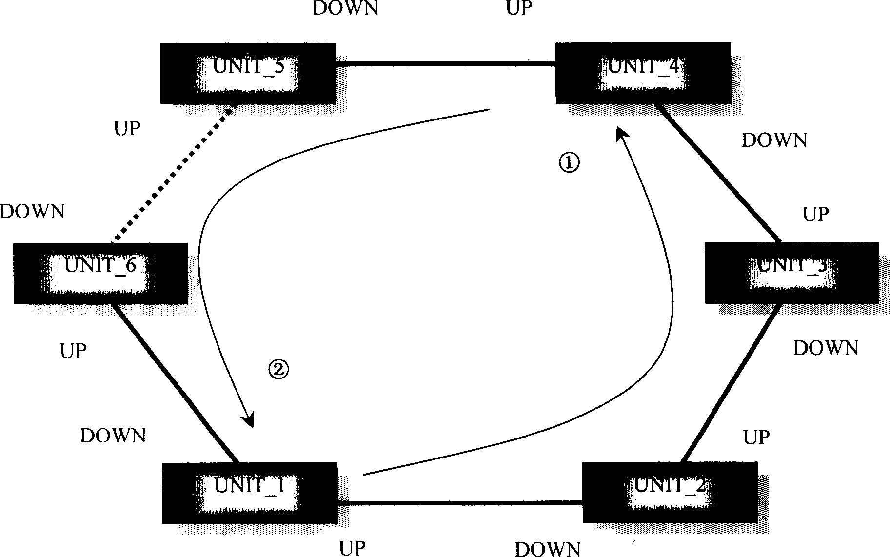
[0031] Specific embodiments of the present invention will be described in detail below in conjunction with the accompanying drawings. The UNIT in the figure is a switching unit device, such as a switch, but not limited to a switch.

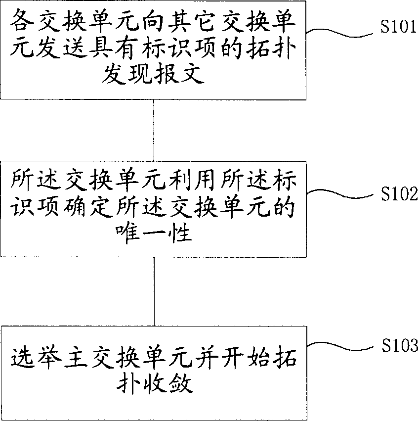
[0032] figure 2 A flow chart of a method for forming a topology structure according to an embodiment of the present invention. Such as figure 2 As shown, after the UNITs are connected to each other by stacking cables, each UNIT sends an Ad message (S101) with an identification item key to other UNITs; each UNIT uses the identification item key to determine the uniqueness of the UNIT (S102); By comparing information with each other, determine the master switching unit and the slave switching unit and start topology convergence (S103); then, the master switching unit sends heartbeat messages to other switching units to form a topology structure.

[0033] In the method for forming the topological structure of the stacking system equipment of the...


PUM


Abstract

The disclosed forming method for topological structure of stack system comprises: arranging two or more exchange units for the system, sending topological message with label item from one unit to another to determine the unique feature of exchange unit, selecting a main unit to send message to other units, beginning topological convergence. This invention improves stack system reliability.

Description

technical field [0001] The invention relates to network technology, in particular to a method for forming a topological structure of stacking system equipment. Background technique [0002] With the popularization of broadband applications and the growth of enterprise information application requirements, the overall speed of the network continues to increase, and the demand for high-throughput data exchange and various intelligent applications is also increasing. In order to make the data switching device meet the port quantity requirements of the large-scale network, it is generally solved by stacking the devices in a large-scale network. Users can connect multiple switching unit devices (UNIT, each UNIT has "UP" and "DOWN" stacking ports at the same time) through the stacking ports to form a ring or chain joint device (Fabric). [0003] In a stacking system, each UNIT needs to have a unique identifier, the source of which is the MAC (Media Access Control, Media Access Co...

Claims


Application Information

Patent Timeline
IPC IPC(8): H04L12/42H04L12/56H04L12/70
Inventor 刘彬
Owner NEW H3C TECH CO LTD
Why Eureka
Try Eureka