Electroplating apparatus

An electroplating device and electroplating tank technology, applied in the electrolysis process, electrolysis components, etc., can solve the problems of electroplating solution pollution, uneven current distribution, and easy aging in advance, and achieve the effect of stable quality and good consistency of coating thickness

Inactive Publication Date: 2007-01-03
CHONGQING YUAN INNOVATION TECH GROUP
View PDF0 Cites 5 Cited by
  • Summary
  • Abstract
  • Description
  • Claims
  • Application Information

AI Technical Summary

Problems solved by technology

Two anode bars are set in each electroplating tank, and the workpiece is hung on the cathode bar between the two anode bars for electroplating. When the workpiece is electroplated in one electroplating tank and enters the next process, the cathode bar and the workpiece pass through other During the electroplating tank, the electroplating solution on the workpiece will drip down on the anode bar, which will cause corrosion to the anode bar, and the electroplating solution will be polluted and easily aged in advance
In addition, because the cathode bar in the same electroplating tank is connected in parallel between the anode bar and the cathode bar, the high-end current of the voltage is large, so the current distribution between the multiple workpieces is uneven, and the two parts of the cathode bar hang on the two sides of the cathode bar. The coating of the workpiece at the end is thicker, which makes the quality of the electroplated products obtained inconsistent

Method used


Image

  • Electroplating apparatus
  • Electroplating apparatus

Examples


Embodiment Construction

[0010] The present invention will be described in further detail below in conjunction with specific embodiments and accompanying drawings.

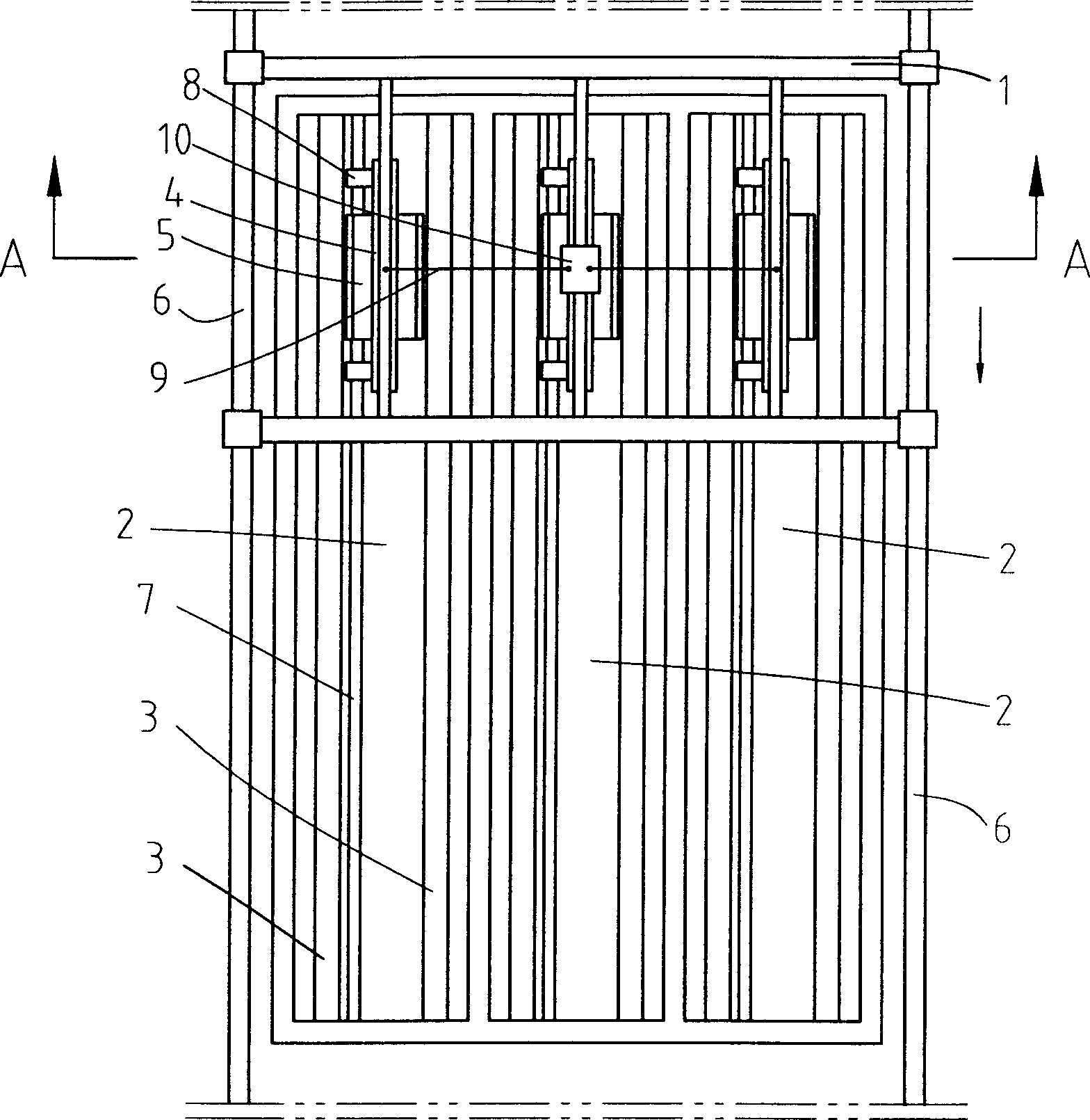
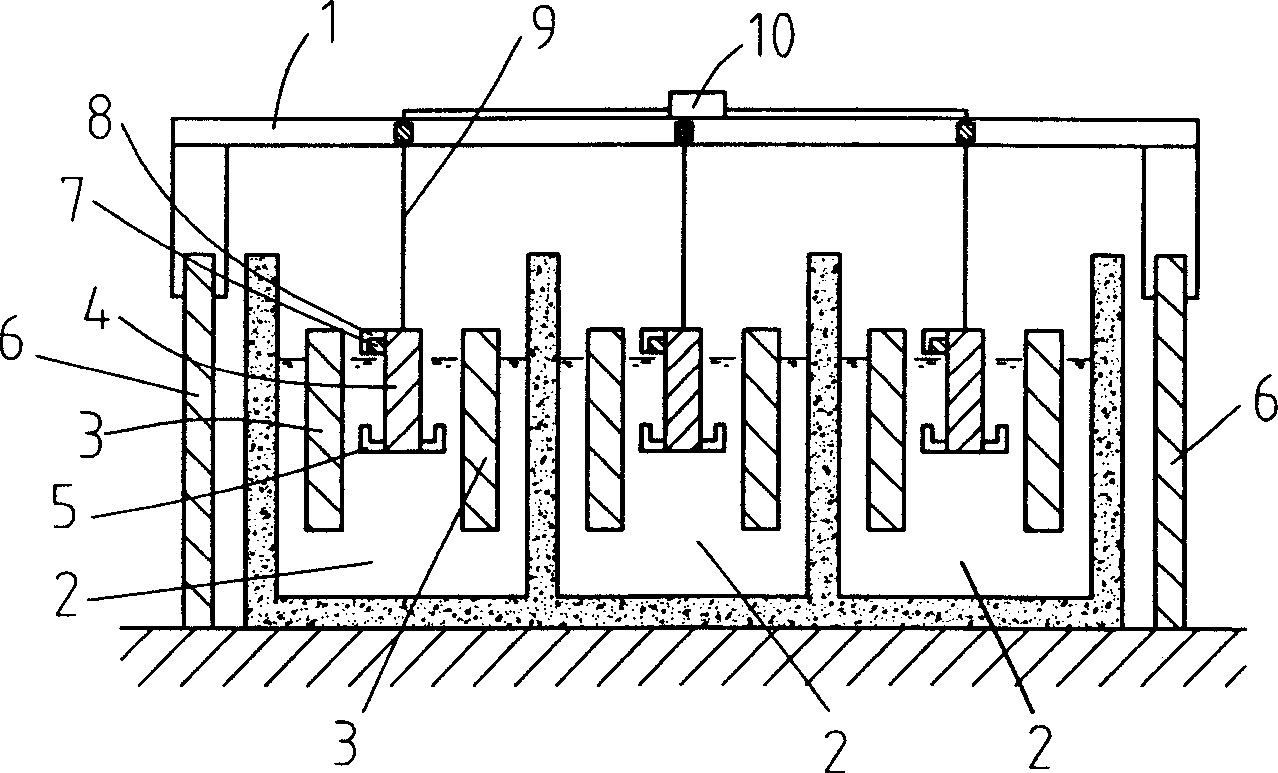
[0011] Such as figure 1 , figure 2 As shown, three electroplating tanks 2 are arranged side by side between the two rails 6 of the driving 1, and two anode bars 3 arranged side by side are installed in each electroplating tank 2, and the workpiece hanger 5 is connected on the cathode bar 4, and the electroplating tank 2 The length direction of the inner anode bar 3 is consistent with the direction of the track 6 of the driving 1, a conductive slide rail 7 is arranged between the two anode bars 3 in the electroplating tank 2, and a conductive sliding sleeve 8 matching the conductive slide rail 7 is arranged on the cathode bar 4. Cathode bar 4 is hung on the lifting mechanism 10 by hanging rope 9, and lifting mechanism 10 is installed on the crane 1, and three cathode bars 4 are connected on the same lifting mechanism 10 by hanging rope 9...


PUM


Abstract

The electroplating apparatus has one or several electroplating baths set between two tracks of traveling crane. Inside the electroplating bath, there are two parallel anode rods parallel to the tracks, one cathode rod with hung workpiece, two conducting slide rails between two anode rods, one conducting slide sleeve on the cathode rod for matching with the slide rails, one elevating mechanism for connecting the cathode rod via a hanging rope to the traveling crane. During electroplating, the cathode rod is driven with the traveling crane to move forward slowly and no corrosive electroplating solution drops from the workpiece to the anode rods. The present invention can obtain homogeneous coating thickness and stable product quality.

Description

technical field [0001] The invention belongs to the technical field of surface treatment, and in particular relates to an electroplating device. Background technique [0002] The principle of electroplating is to rectify the three-phase alternating current into low-voltage, high-current direct current through a high-power rectifier, connect the anode of the power supply to the anode bar insoluble in the electroplating solution, hang the workpiece to be plated on the cathode bar, and electroplate the ion The movement in the plating solution produces an electroplating layer on the surface of the product to be plated. At present, in various electroplating production lines, in order to improve production efficiency, several mutually independent electroplating tanks are usually arranged side by side along the traveling direction of the vehicle to simultaneously electroplate multiple workpieces. Two anode bars are set in each electroplating tank, and the workpiece is hung on the ...

Claims


Application Information

Patent Timeline
Patent Type & Authority Applications(China)
IPC IPC(8): C25D17/00
Inventor 张兴海邹贵钦
Owner CHONGQING YUAN INNOVATION TECH GROUP
Why Eureka
Try Eureka