Bearing device for wheel

A bearing device and wheel technology, applied in the directions of axles, wheels, roller bearings, etc., can solve the problems of complicated assembly and large number of parts, and achieve the effects of low cost, improved durability, and increased bearing rigidity

Active Publication Date: 2007-01-03
NTN CORP
View PDF1 Cites 14 Cited by
  • Summary
  • Abstract
  • Description
  • Claims
  • Application Information

AI Technical Summary

Problems solved by technology

[0006] However, such a conventional wheel bearing device is configured such that a plurality of rows of tapered rolling bearings 53 are installed between a wheel hub 54 and an axle tube 51, and a drive shaft 52 is penetrated through the a

Method used


Image

  • Bearing device for wheel
  • Bearing device for wheel
  • Bearing device for wheel

Examples


Embodiment 1

[0035] Hereinafter, embodiments of the present invention will be described in detail with reference to the drawings.

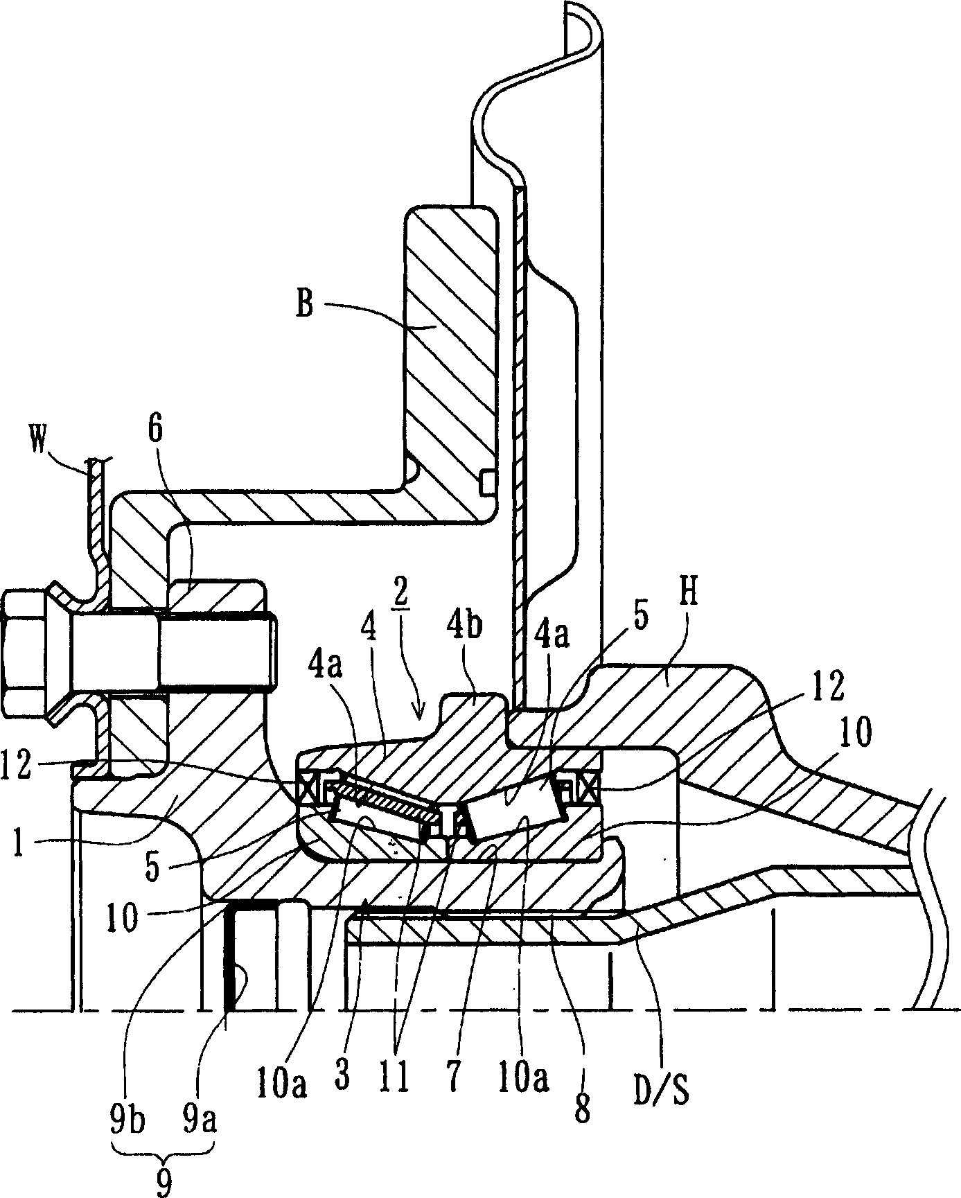
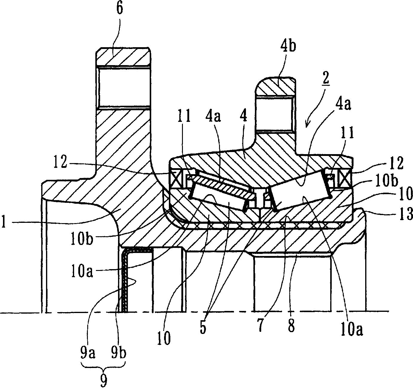
[0036] figure 1 It is a longitudinal sectional view showing the first embodiment of the wheel bearing device according to the present invention, figure 2 It is a longitudinal sectional view showing the wheel bearing. In addition, in the following description, in the state mounted on the vehicle, the side closer to the vehicle outer side is referred to as the vehicle outer side (left side in the figure), and the side closer to the center is referred to as the vehicle inner side (right side in the figure). ).

[0037] The wheel bearing device is composed of a wheel hub 1 and a multi-row rolling bearing 2 and is connected to the drive shaft D / S. The multi-row rolling bearing 2 has an inner member 3 , an outer member 4 , and multi-row rolling elements (tapered rollers) 5 , 5 rotatably housed between the two members 3 , 4 . Here, the inner member 3 refers to ...

Embodiment 2

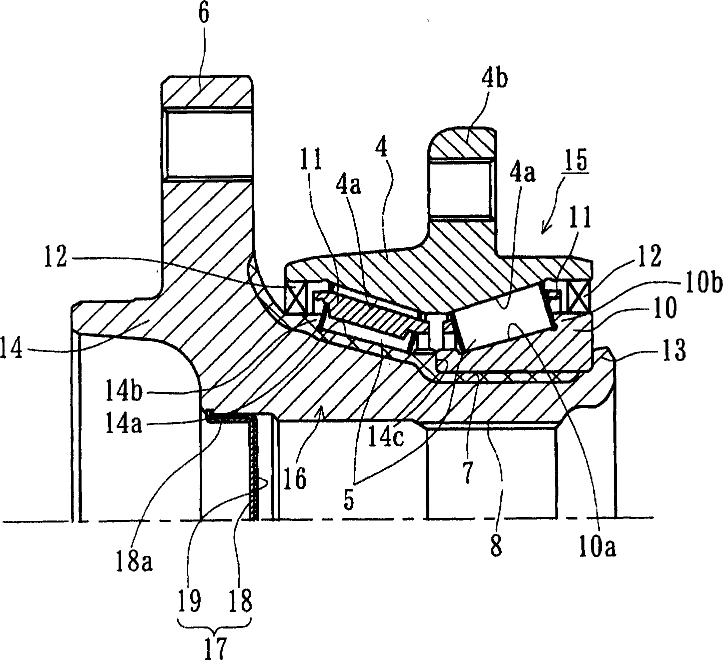
[0045] image 3 It is a longitudinal sectional view showing a second embodiment of the wheel bearing according to the present invention. In this embodiment, only the hub structure is different from the above-mentioned embodiment, so the same reference numerals are assigned to the same parts as those in the first embodiment above, and detailed description thereof will be omitted.

[0046] This wheel bearing is composed of a hub 14 and a multi-row rolling bearing 15 combined. The multi-row rolling bearing 15 has an inner member 16 , an outer member 4 , and multi-row rolling elements 5 , 5 rotatably accommodated between the two members 16 , 4 . Herein, the inner part 16 refers to the hub 14 and the inner ring 10 pressed into the hub 14 . The wheel hub 14 has a wheel mounting flange 6 integrated therewith, and the wheel mounting flange 6 is used to install a wheel (not shown) on the outer side end of the outer periphery. The raceway surface 14a and the cylindrical portion 7 axi...

Embodiment 3

[0052] Figure 5 It is an enlarged view of main parts showing a third embodiment of the wheel bearing according to the present invention. The same reference numerals are assigned to the same parts, the same parts, the same functions, and the like as those in the aforementioned embodiment, and detailed description thereof will be omitted.

[0053] In the present embodiment, the cover 21 is press-fitted into the opening of the vehicle outer end portion of the hub 1 . The cover 21 is composed of a steel plate mandrel 21a and an elastic member 21b. The mandrel 21a is formed by stamping an austenitic stainless steel plate (JIS standard SUS304 series, etc.) or a rust-proof cold-rolled steel plate (JIS standard SPCC series, etc.). ) is formed in a substantially U-shaped cross section, and a part of the elastic member 21b bulges from the inner peripheral surface of the mandrel 21a at the fitting portion. The elastic member 21b is made of rubber or the like bonded by vulcanization, a...


PUM


Abstract

A bearing device for a wheel enabling a reduction in weight and size and the number of parts and capable of preventing rain water and dust from entering therein and differential gear oil from leaking, comprising an inside member (3) having a hub wheel (1) in which a bearing for the wheel is installed in an opening part between an axle tube (H) supported on the lower surface of a vehicle body and a drive shaft (D/S) inserted into the axle tube and the bearing for the wheel is formed integrally with a wheel mounting flange (6) at one end and a cylindrical part (7) is formed thereon and an inner ring (10) press-fitted into the cylindrical part (7), an outer member (4) inserted onto the inner member (3), and multiple rows of rolling elements (5) rollingly stored between the inner member (3) and the outer member (4). The inner ring (10) is prevented from coming off in the axial direction by a clamping part (13) formed by elastically deforming the end part of the cylindrical part (7) in the radial outer direction. A cap (9) formed of a steel plate core (9a) formed in a generally channel shape in cross section and an elastic member (9b) joined to the fitting part of the core (9a) is press-fitted into the inner diameter part of the wheel mounting flange (6).

Description

technical field [0001] The present invention relates to a bearing device for a wheel which supports a wheel of an automobile etc. so that it can freely rotate relative to a suspension device, and more particularly relates to a bearing device for a semi-floating wheel which supports a driving wheel by using a multi-row rolling bearing. Background technique [0002] In vehicles with a frame structure such as trucks, a full-floating axle has conventionally been used as the axle structure of the drive wheels. Recently, the supporting structure of the driving wheel is to improve the assemblability, reduce the weight, compactness, etc., and a structure in which multiple rows of rolling bearings are unitized is often used. As an example of such a conventional structure, it has been known as Figure 9 The bearing assembly for the wheel shown. [0003] In this wheel bearing device, a drive shaft 52 connected to a differential (not shown) penetrates an axle tube 51 , and a multi-row ...

Claims


Application Information

Patent Timeline
IPC IPC(8): B60B35/14B60B35/18F16C19/38F16C35/063
Inventor 河村浩志重冈和寿藤村启西野晃司大槻寿志
Owner NTN CORP
Why Eureka
Try Eureka