Method of stretching optical fiber base material and stretching device

A technology for drawing equipment and substrates, applied in glass manufacturing equipment, optics, light guides, etc., can solve the problems of poor dimensional accuracy of optical fiber substrates or preforms, so as to increase production, reduce manufacturing costs, and reduce time consumption. and gas effect

Inactive Publication Date: 2007-01-03
SHIN ETSU CHEM CO LTD
View PDF0 Cites 16 Cited by
  • Summary
  • Abstract
  • Description
  • Claims
  • Application Information

AI Technical Summary

Problems solved by technology

[0004] However, the dimensional accuracy of optical fiber substrates or preforms obtained by drawing processes using electric furnaces with larger heating zones is poorer than that obtained by drawing processes using heating burners

Method used


Image

  • Method of stretching optical fiber base material and stretching device
  • Method of stretching optical fiber base material and stretching device
  • Method of stretching optical fiber base material and stretching device

Examples


example 1

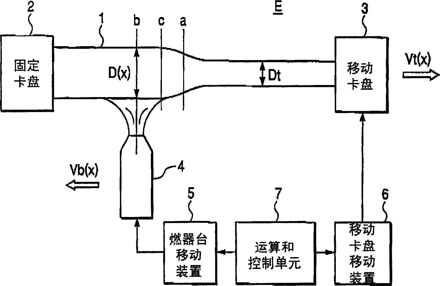
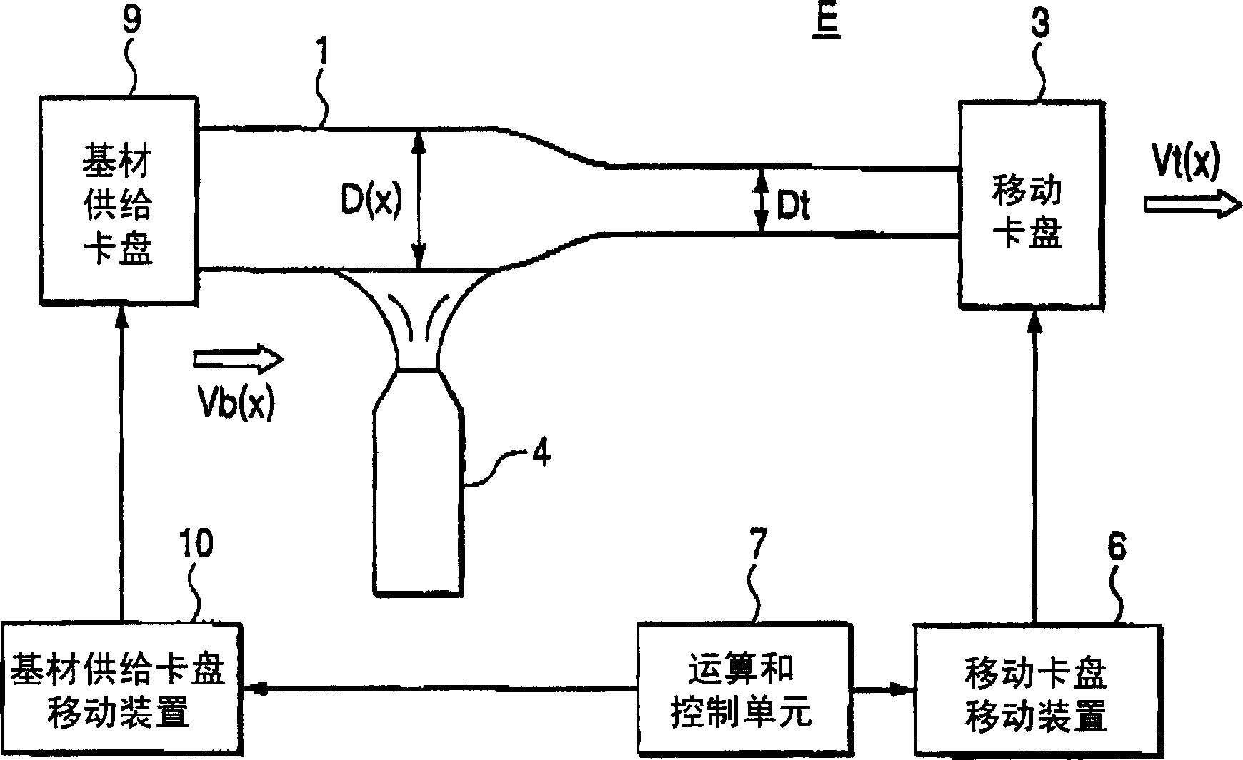
[0102] As a starting substrate, an optical fiber substrate having an outer diameter varying in the longitudinal direction in the range of 75 mm to 96 mm was used. For the heating burner 4, hydrogen gas was supplied as combustible gas at a rate of 390 l (liter) / min, and oxygen gas was supplied as combustion gas at a rate of 160 l / min, respectively, and heating control was performed so that the maximum surface temperature at the heating portion was about 2100 Celsius. A portion of the optical fiber substrate having a diameter of 85 mm was set as a stretching start end, and a target stretching outer diameter was set to 75 mm. According to experience, the reference moving speed Vb of the heating burner is set to 6.9mm / min.

[0103] When the diameter of the starting substrate at position x along the longitudinal direction is D(x), the maximum outer diameter of the starting substrate is D max , and when the target stretching outer diameter is Dt, calculate the target moving speed ...


PUM


Abstract

A method of stretching an optical fiber base material comprising the step of gripping the opposite ends in a length-wise direction of an optical fiber base material with a pair of grip tools and moving one or both of the pair of grip tools in a first direction parallel to the above length-wise direction to thereby pull the optical fiber base material while moving a heating device relatively to the optical fiber base material in a second direction opposite to the first direction; and a device therefore; wherein the above optical fiber base material is stretched while the above relative moving speed Vb(x) is changed according to the expression (1): Vb.[Dmax / D(x)]<2> <= Vb(x) <= Vb.[Dmax / D(x)]<3> (1), in the expression, Vb denotes a reference speed, Dmax the maximum outer diameter of the optical fiber base material, D(x) the outer diameter of the optical fiber base material at a heated position x, and Vb(x) the moving speed of a heating device relative to the optical fiber base material when the optical fiber base material is at a heated position x.

Description

technical field [0001] The present invention relates to a drawing method of an optical fiber base material for drawing the optical fiber base material to a desired outer diameter while heating and softening the optical fiber, and relates to a drawing device for realizing the method. Background technique [0002] Optical fibers are manufactured by drawing an optical fiber base material (preform). A preform is obtained by subjecting an optical fiber base material (starting base material) having an outer diameter that varies relatively greatly in the longitudinal direction to a drawing process of drawing it to a desired outer diameter while being heated and softened. As the heating means, a heating burner that burns with combustible gas such as oxygen, hydrogen, and propane, and an electric furnace using a resistance heater are used. [0003] In recent years, in order to increase the productivity of optical fibers, there has been a tendency to use a larger starting base materi...

Claims


Application Information

Patent Timeline
Patent Type & Authority Applications(China)
IPC IPC(8): C03B37/012
CPCC03B37/01242Y02P40/57G02B6/00
Inventor 铃木真二山村和市
Owner SHIN ETSU CHEM CO LTD
Why Eureka
Try Eureka