
Rubber plastic strip tensile capacity detection device

A detection device and a technology for plastic strips, which are applied in the field of rubber manufacturing, can solve the problems of insufficient fixation and low measurement accuracy, and achieve the effects of accurate tensile property measurement, improved stability, and convenient fixation.

Active Publication Date: 2020-09-11
SUZHOU CANGMIN EIECTRONIC TECH CO LTD
View PDF4 Cites 5 Cited by
  • Summary
  • Abstract
  • Description
  • Claims
  • Application Information

AI Technical Summary

Problems solved by technology

The existing detection device is not stable enough to fix the rubber and plastic strips, and the measurement accuracy is low. Therefore, in view of the above situation, it is urgent to develop a method that is convenient for fixing the rubber and plastic strips and can accurately measure the tensile properties of the rubber and plastic strips. Detection device to overcome the deficiencies in the current practical application and meet the current needs

Method used


Image

  • Rubber plastic strip tensile capacity detection device
  • Rubber plastic strip tensile capacity detection device
  • Rubber plastic strip tensile capacity detection device

Examples


Embodiment 1

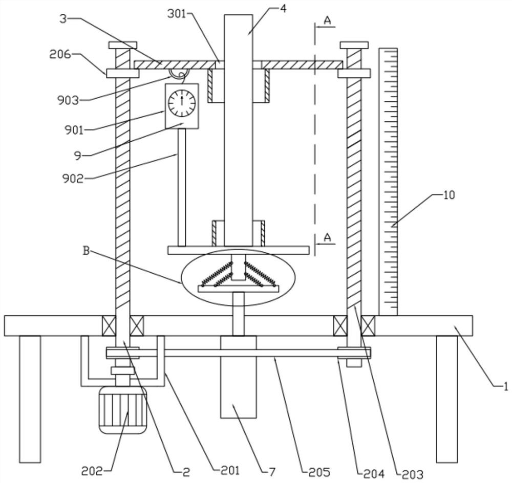
[0021] see Figure 1~4 , in an embodiment of the present invention, a rubber and plastic strip tensile capacity detection device includes a workbench 1, a height adjustment device 2 is installed on the workbench 1, a lifting plate 3 is installed on the height adjustment device 2, and the Said height adjustment device 2 comprises: frame 201, servo motor 202, ball screw 203, synchronous wheel 204, synchronous belt 205 and slide block 206, and described frame 201 is installed on the lower side of workbench 1, and described frame Servo motor 202 is installed on 201, two ball screws 203 are connected in rotation on the workbench 1, and a synchronous wheel 204 is respectively installed on the two ball screws 203, and the two synchronous wheels 204 are synchronized by The belt 205 is rotationally connected, and a slider 206 is installed on the two ball screws 203 respectively, and a lifting plate 3 is connected between the two sliders 206, and the output shaft of the servo motor 202 ...

Embodiment 2

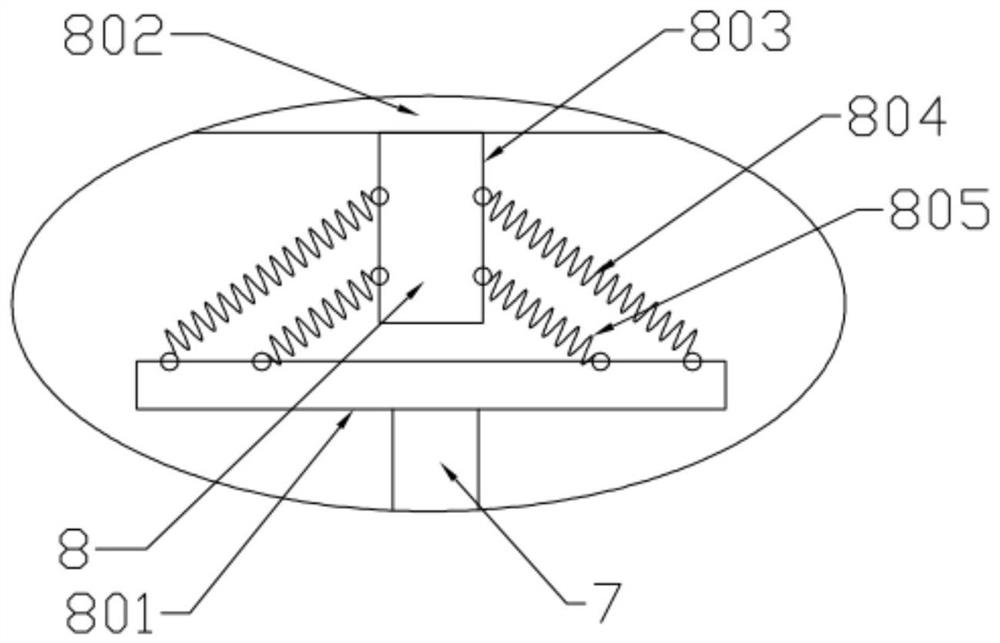
[0023] see figure 1 , in the embodiment of the present invention, the tension measuring device 9 includes: a tension gauge 901, a pull wire 902 and a suspension ring 903, the top of the tension gauge 901 is connected to the suspension ring 903, and the suspension ring 903 is installed on the bottom of the lifting plate 3, so A pull wire 902 is installed on the bottom of the tension gauge 901, and the bottom of the pull wire 902 is connected to the support plate 802, and the length of the pull wire 902 can be adjusted.

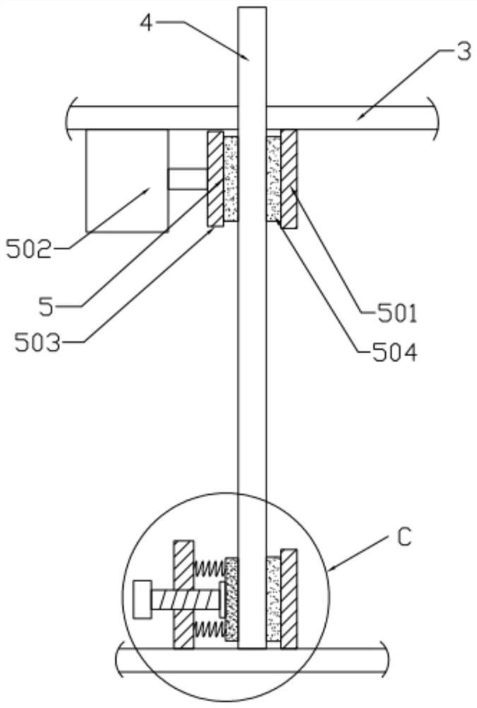
[0024]In this rubber and plastic strip tensile capacity detection device, the rubber and plastic strip 4 is put into the manual clamping device 6 through the lifting plate 3, and the ball screw 203 is driven by the servo motor 202 to rotate, and the ball screw 203 is rotated to drive the slide. The block 206 moves up and down, the lifting plate 3 moves up and down by the sliding block 206 moving up and down, the fixed position of the rubber plastic strip 4 is a...


PUM


Abstract

The invention discloses a rubber plastic strip tensile capacity detection device comprising a workbench; and a height adjusting device is installed on the workbench. A lifting plate is mounted on theheight adjusting device; a rubber plastic strip is mounted on the lifting plate; an automatic clamping mechanism is installed on the lower side of the lifting plate, a hydraulic cylinder is installedon the workbench and located below the lifting plate, the hydraulic cylinder is connected with a buffer mechanism, a manual clamping device is installed at the top of the buffer mechanism, the bottomof the rubber plastic strip is fixed in the manual clamping device, and a tension measuring device is connected between the lifting plate and the buffer mechanism. According to the invention, the rubber plastic strip is convenient to fix, and the tensile property of the rubber plastic strip is accurately measured.

Description

technical field [0001] The invention relates to the technical field of rubber manufacturing, in particular to a device for detecting the tensile capacity of rubber and plastic strips. Background technique [0002] Rubber refers to a highly elastic polymer material with reversible deformation. It is elastic at room temperature, can produce large deformation under a small external force, and can return to its original shape after the external force is removed. Rubber is a completely amorphous polymer with a low glass transition temperature and often a large molecular weight, greater than hundreds of thousands. Rubber is divided into two kinds of natural rubber and synthetic rubber. [0003] After the rubber is produced, its tensile properties need to be tested to ensure that it can meet the requirements of use. The existing detection device is not stable enough to fix the rubber and plastic strips, and the measurement accuracy is low. Therefore, in view of the above situatio...

Claims


Application Information

Patent Timeline
Patent Type & Authority Applications(China)
IPC IPC(8): G01N3/04G01N3/10G01N3/06
CPCG01N3/04G01N3/10G01N3/062G01N2203/0003G01N2203/0017G01N2203/0048G01N2203/0411G01N2203/0605
Inventor 何卫华
Owner SUZHOU CANGMIN EIECTRONIC TECH CO LTD
Learn More