Controlling system for cooling fan

A cooling fan and control system technology, applied in the direction of coolant flow control, engine cooling, fluid pressure actuation device, etc., can solve problems such as unpleasantness, engine power consumption fluctuations, operator insecurity, etc., to achieve significant reduction Effect of changing and stabilizing operating power

Inactive Publication Date: 2007-01-10
KOBELCO CONSTR MASCH CO LTD
View PDF1 Cites 14 Cited by
  • Summary
  • Abstract
  • Description
  • Claims
  • Application Information

AI Technical Summary

Problems solved by technology

This can cause dramatic changes in fan noise in response to each change in motor speed, giving the operator an unsafe and unpleasant feeling
[0006] In addition, significant changes in motor speed between high and low speed modes cause large fluctuations in engine power consumption for cooling fans
Since this significantly changes the power available for excavator operation (engine power, fan power), the operating speed of the connected parts changes, thus compromising the excavator's operational performance

Method used


Image

  • Controlling system for cooling fan
  • Controlling system for cooling fan
  • Controlling system for cooling fan

Examples


Embodiment Construction

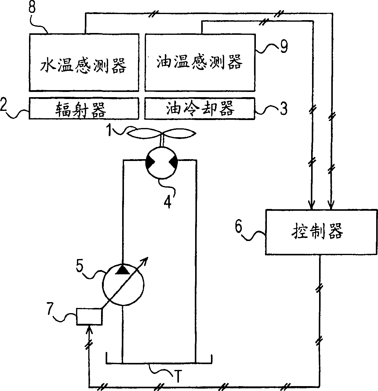
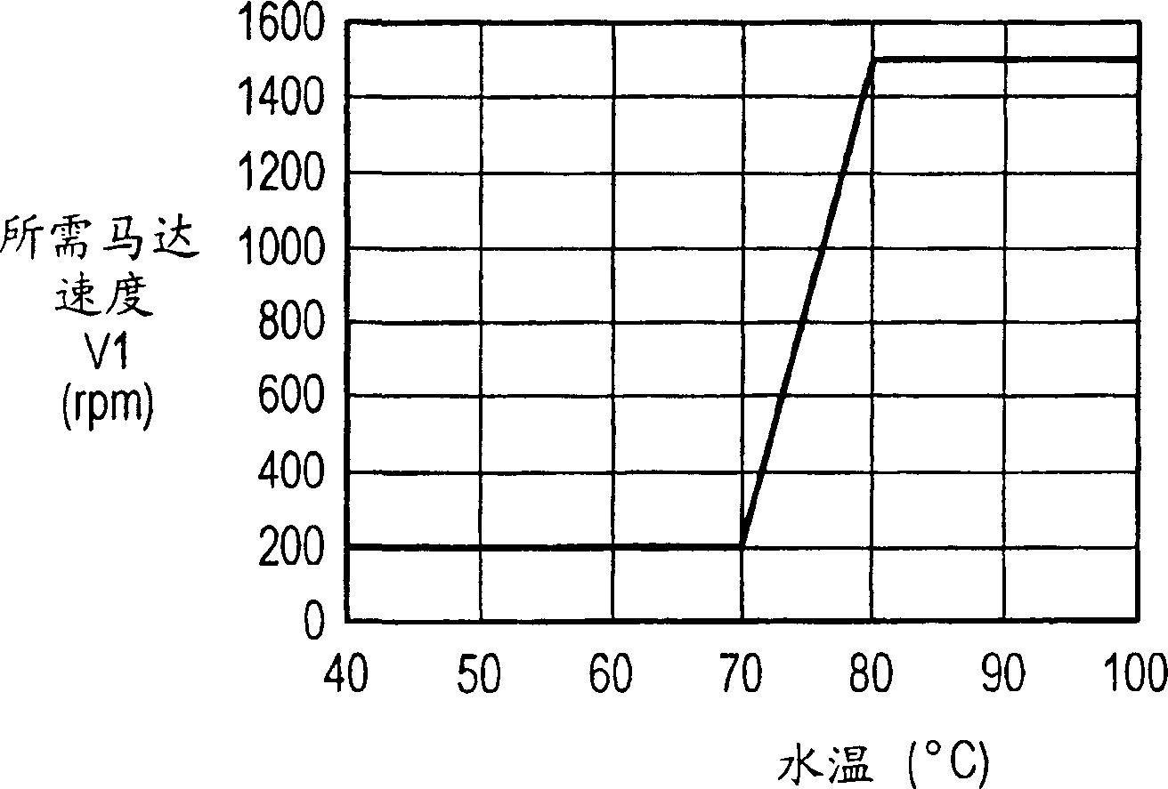
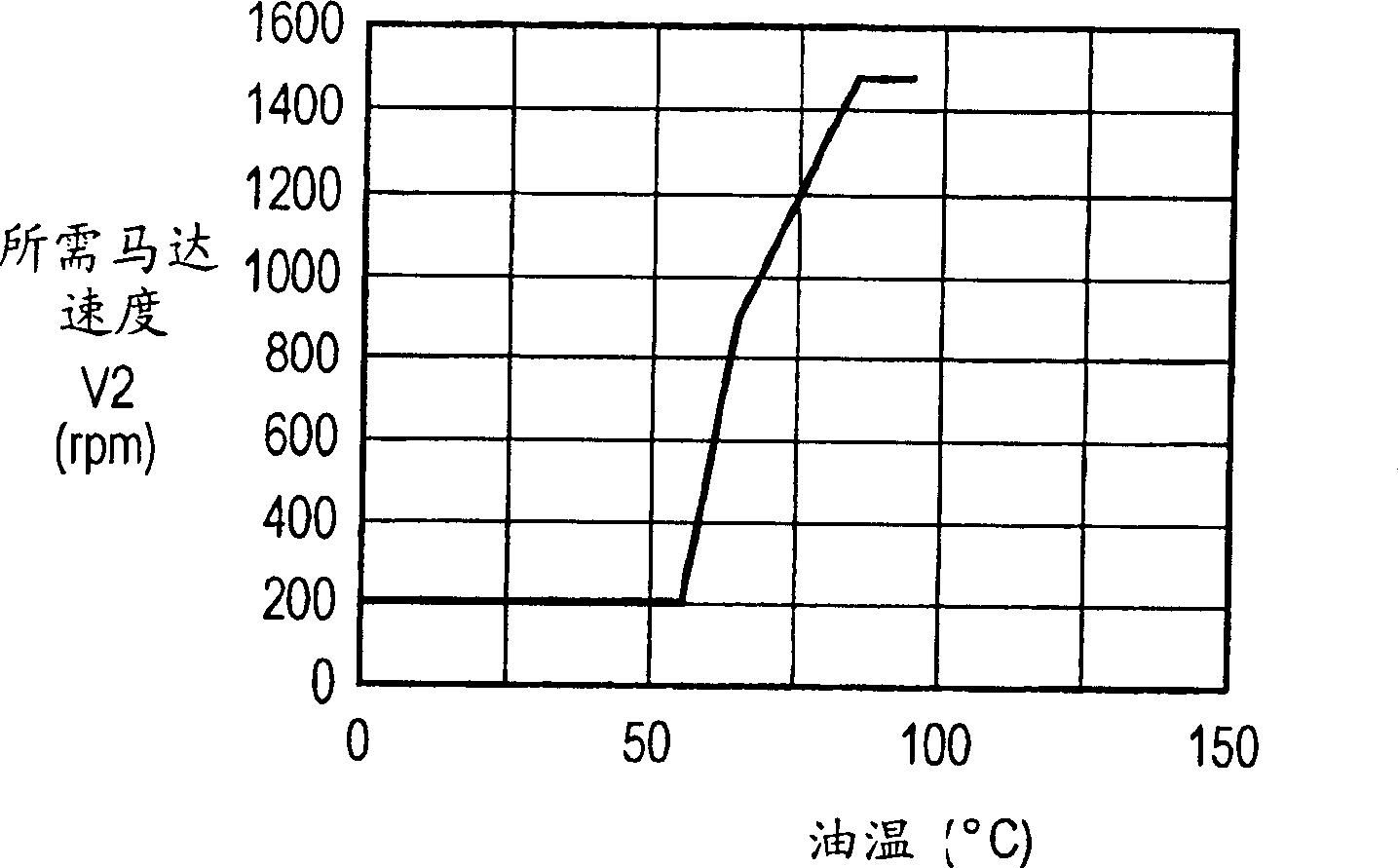
[0018] The following description is directed to an example in which the present invention is used for a hydraulic excavator driven hydraulically by, for example, fluid pressure. The hydraulic excavator is equipped with, for example, an engine cooling device for cooling an engine; a working oil cooling device for cooling working oil used to actuate a hydraulic actuator serving as a fluid pressure actuator; and a driver cooling device for cooling the interior of a cab. room cooling unit. In addition, these cooling devices are individually provided with cooling fans, or are provided with a common cooling fan. The cooling fan is rotated by a hydraulic motor serving as a fluid pressure motor hydraulically driven by a hydraulic pump as a fluid pressure pump. The control system for a cooling fan according to the invention is used as such a cooling fan.

[0019] A control system for a cooling fan according to an exemplary embodiment of the present invention will now be described wit...


PUM


Abstract

A controlling system for a cooling fan according to the present invention includes a fluid-pressure motor for driving the cooling fan; a fluid-pressure pump functioning as a driving source for the fluid-pressure motor; and a controller. The controller determines a target motor speed value by selecting a higher one of required motor speed values respectively corresponding to multiple kinds of fluids to be cooled and controls the fluid-pressure motor so that the motor speed thereof reaches the target motor speed value, each of the required motor speed values being determined from a temperature value of the corresponding fluid detected by a corresponding one of temperature sensors on the basis of a characteristic preliminarily determined by a temperature-versus-motor-speed relationship for the corresponding fluid, the characteristic being set for each kind of fluid.

Description

technical field [0001] The invention relates to a control system for a cooling fan driven by a hydraulic motor. Background technique [0002] For example, Japanese Patent No. 3238775 discloses a technique for preventing energy waste in a driving system of a hydraulic motor rotating a cooling fan of an engine cooling device and a working oil cooling device arranged in a hydraulic excavator. In particular, this is achieved by switching the hydraulic motor rotational speed between high and low speed modes according to the temperature of the fluid to be cooled. [0003] According to this technique, the motor is rotated at high speed when the temperature values ​​of cooling water and working oil for the motor are higher than predetermined temperature values, and the motor is rotated at low speed when these temperature values ​​are lower than predetermined temperature values. [0004] However, since the control operation in this technique is only used to increase or decrease the ...

Claims


Application Information

Patent Timeline
Patent Type & Authority Applications(China)
IPC IPC(8): F01P7/04F15B11/02
CPCF01P7/044F01P2025/40F01P2025/52F01P2025/34F01P2060/04
Inventor 早乙女吉美
Owner KOBELCO CONSTR MASCH CO LTD
Why Eureka
Try Eureka