
Valve plate and hydraulic apparatus with the same

A technology of hydraulic device and valve plate, applied in the field of hydraulic device, can solve the problems of large pressure fluctuation speed of piston chamber 6, damage of valve plate 2 and cylinder port 7, damage of valve plate cylinder port 7, etc., so as to prevent pulsation and prevent injection. The effect of small flow in the flow and discharge pipes

Active Publication Date: 2007-01-10
KAWASAKI HEAVY IND LTD
View PDF1 Cites 9 Cited by
  • Summary
  • Abstract
  • Description
  • Claims
  • Application Information

AI Technical Summary

Problems solved by technology

In this state, when the opening area of ​​the suction port 3 is large, the efficiency of the pump decreases due to the large flow rate flowing in the reverse direction from the discharge port 4 to the suction port 3, and the pressure fluctuation rate of the piston chamber 6 is large. thus increasing the vibration
In addition, when the opening area of ​​the suction port 3 is relatively small, if the pressure difference between the cylinder port 7 and the suction port 3 is relatively large for a relatively small opening area, the flow rate of the working oil flowing in the reverse direction increases, resulting in The jet flow produces a large noise and causes damage to the valve plate 2 and the cylinder port 7
Also, in the case where the suction port 3 and the discharge port 4 are not connected by the cylinder port 7, after the discharge port 4 and the cylinder port 7 are cut off, the working oil in the piston chamber 6 is compressed by the piston 8, and the pressure of the working oil When the pressure becomes high, more noise occurs due to the connection with the suction port 3, and the valve plate 2 and the cylinder port 7 are obviously damaged.

Method used


Image

  • Valve plate and hydraulic apparatus with the same
  • Valve plate and hydraulic apparatus with the same
  • Valve plate and hydraulic apparatus with the same

Examples


Embodiment Construction

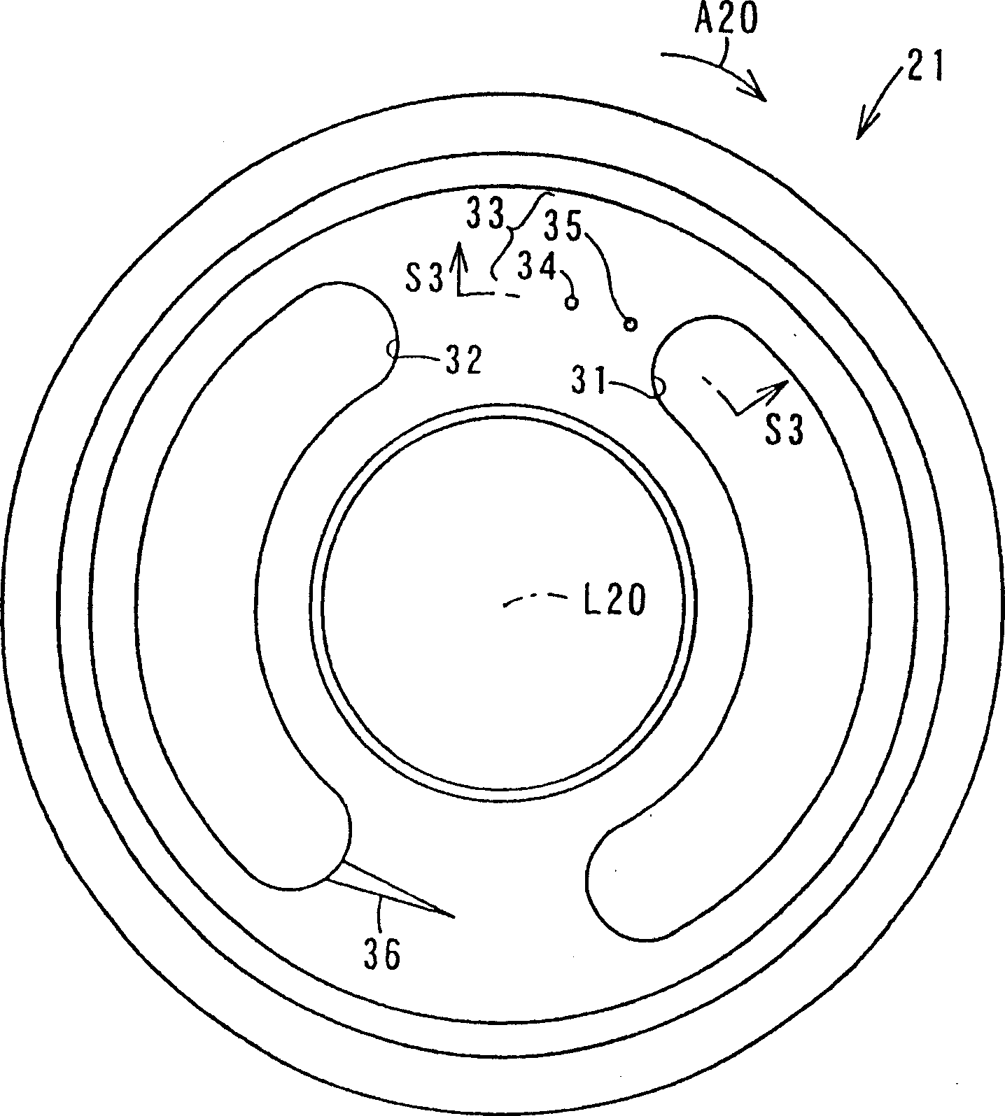
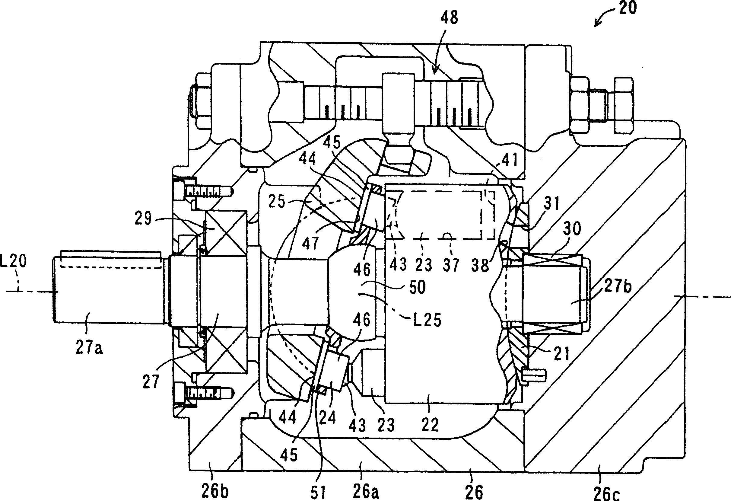
[0059] figure 1 It is a front view of the valve plate 21 of the piston pump 20 which concerns on one Embodiment of this invention. figure 2 is a sectional view of the piston pump 20 . figure 1 means from as figure 2 The valve plate 21 viewed from the cylinder block 22 side on the left. The piston pump 20 as a hydraulic device is a variable capacity swash plate type hydraulic pump installed on, for example, industrial machinery and construction machinery, and is driven by a driving force from a prime mover to supply working oil as a working fluid to the hydraulic pump. Installed in the driver of industrial machinery and construction machinery, and used to drive the driver. Such a piston pump 20 basically includes a valve plate 21 , a cylinder block 22 , a plurality of pistons 23 , a plurality of gates 24 , and a swash plate 25 , and these components are housed in a housing 26 that the piston pump 20 also includes. The housing 26 has a housing main body 26a, a front cove...


PUM


Abstract

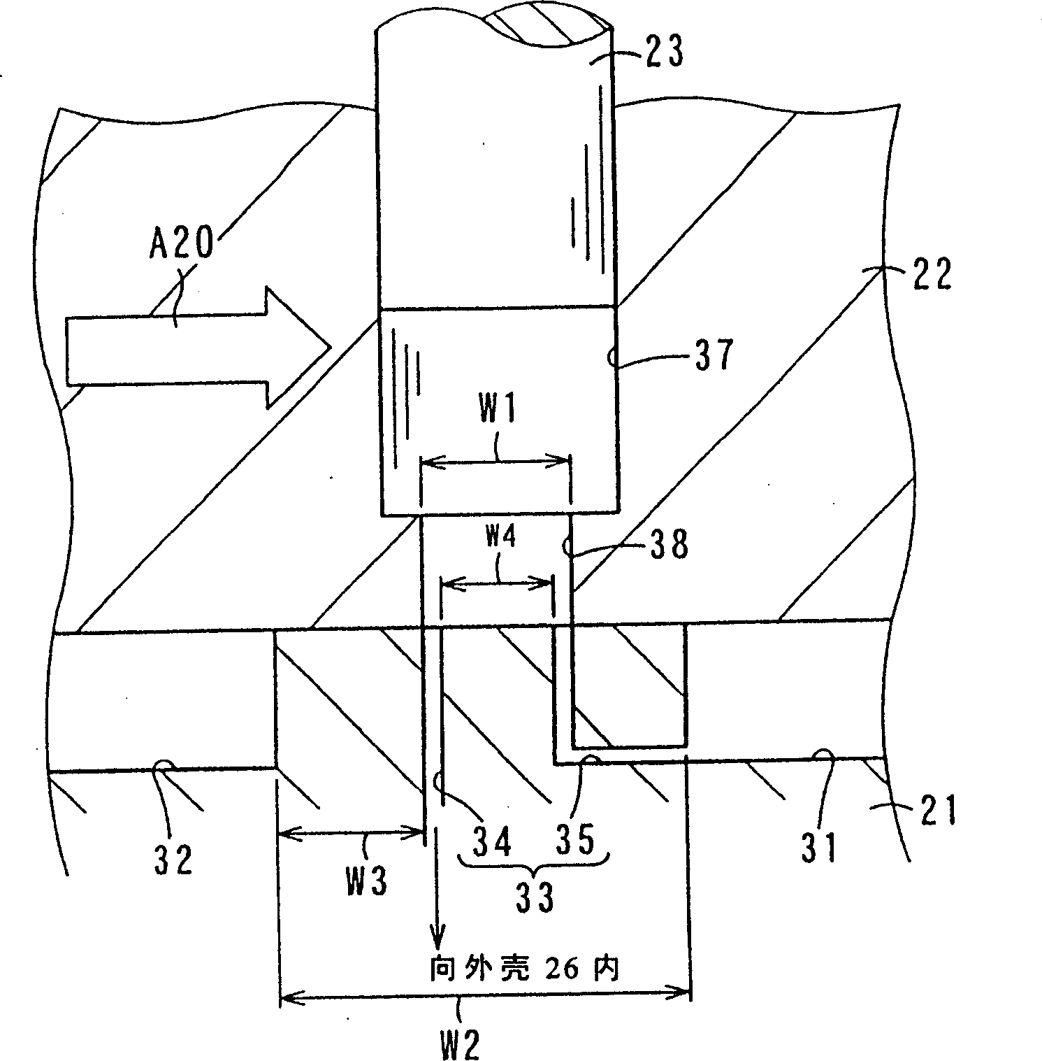
Provided an efficient valve plate capable of keeping noise low and a hydraulic device provided with the same. A pressure release port 33 including a first and a second pressure release hole 34, 35 is formed on an upstream side of a rotary direction A20 of a cylinder block 22 in relation of an intake port 31 on the valve plate 21. The pressure release port 33 opens a cylinder port in multiple steps, and discharges working fluid in a piston chamber 37 before the piston chamber 37 is connected to the intake port 31. Consequently, jet is prevented from occurring when the piston chamber 37 is connected to the intake port 31, noise can be prevented and cavitation damage of the valve plate 21 can be prevented.

Description

technical field [0001] The present invention relates to a hydraulic device suitable as a valve plate realized by a piston pump and a piston hydraulic motor, and particularly relates to a valve plate provided in the hydraulic device. Background technique [0002] Figure 7 is a front view of the valve plate 2 of a prior art piston pump. Figure 8 From Figure 7 A cross-sectional view of a part of the piston pump obtained by observing section line S8-S8. Figure 8 The upper development represents an arc-shaped cross section extending in the circumferential direction. The piston pump includes a cylinder block 5 provided rotatably in a rotation direction A1 around an axis L1. A plurality of piston chambers 6 are formed in the cylinder block 5 , and cylinder ports 7 communicating with each of the piston chambers 6 are respectively formed. A piston 8 is fitted into each piston chamber 6 . A brake shoe is provided at one end of each piston, and each brake shoe is pressed agains...

Claims


Application Information

Patent Timeline
Patent Type & Authority Applications(China)
IPC IPC(8): F04B53/10
CPCF04B1/2042F04B1/122F04B53/1087F04B53/001
Inventor 吉村勇大西正贵
Owner KAWASAKI HEAVY IND LTD
Learn More