Method for machining blade compressor

A processing method and compressor technology, applied in metal processing equipment, manufacturing tools, milling machine equipment details, etc., can solve problems such as no processing method, refrigerant leakage, poor sealing effect, etc., and achieve the effect of improving the sealing effect

Inactive Publication Date: 2007-01-17
LG ELECTRONICS (TIANJIN) APPLIANCES CO LTD
View PDF0 Cites 2 Cited by
  • Summary
  • Abstract
  • Description
  • Claims
  • Application Information

AI Technical Summary

Problems solved by technology

[0009] But in above-mentioned existing processing method, used standard upright end cutter tool in order to process blade 5, but the central part velocity of this standard upright end cutter tool 10 is zero, and the low-end complementary angle θ is bigger, so to machined surface, promptly with The vane 5 forms a right angle, and the outer peripheral edge of the bearing part 4a that contacts the inner surface of the vane 6A, 6B forms an uneven surface like a bolt, so the sealing effect with the vane 6A, 6B is not good, and there is a possibility of refrigerant leakag

Method used


Image

  • Method for machining blade compressor
  • Method for machining blade compressor
  • Method for machining blade compressor

Examples


Example Embodiment

[0029] In order to further explain the technical means and effects that the present invention takes to achieve the intended purpose of the invention, the specific implementation and processing method of the blade processing method of the vane compressor proposed according to the present invention will be described below in conjunction with the accompanying drawings and preferred embodiments. , steps, features and effects thereof are described in detail below.

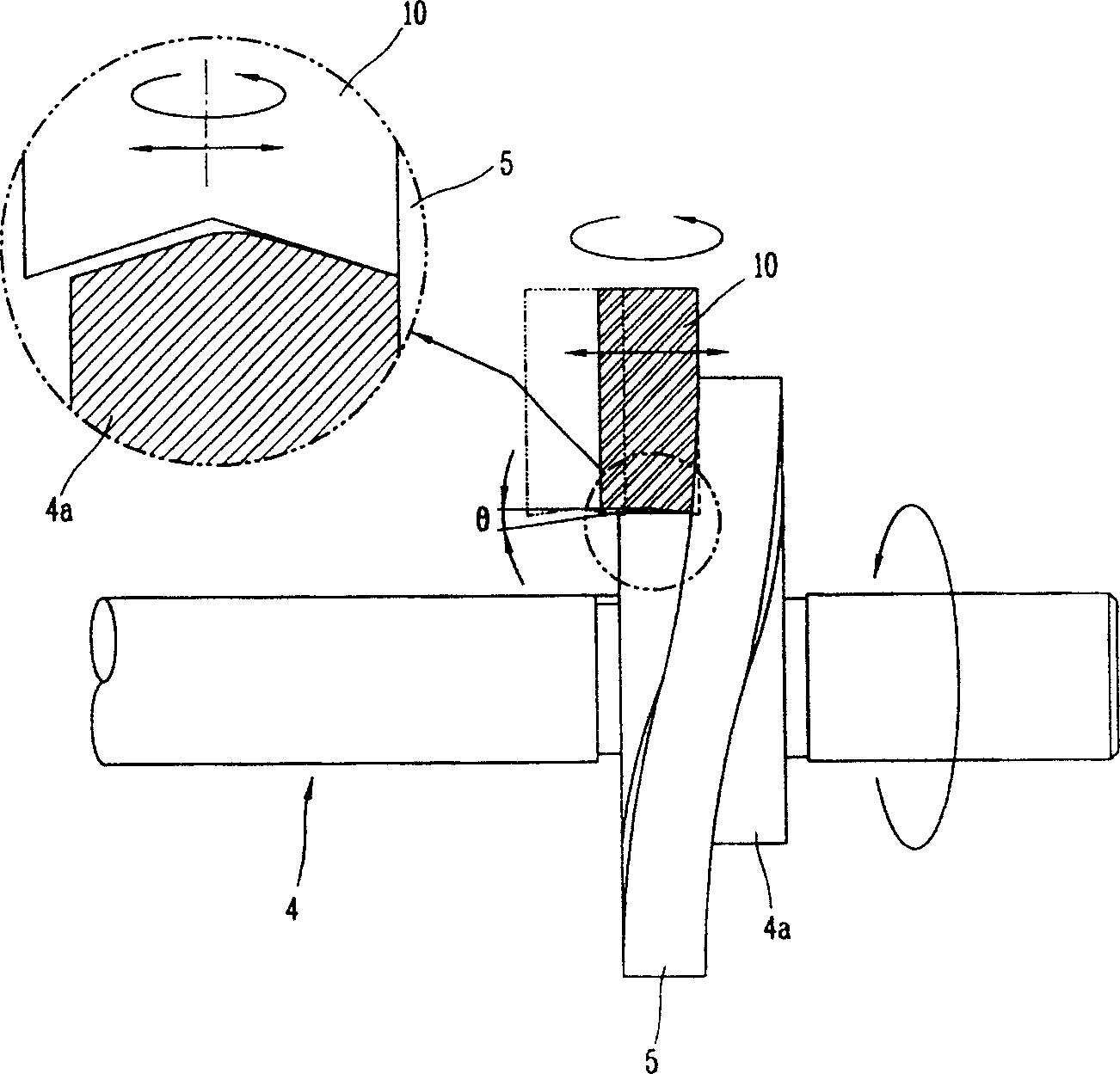
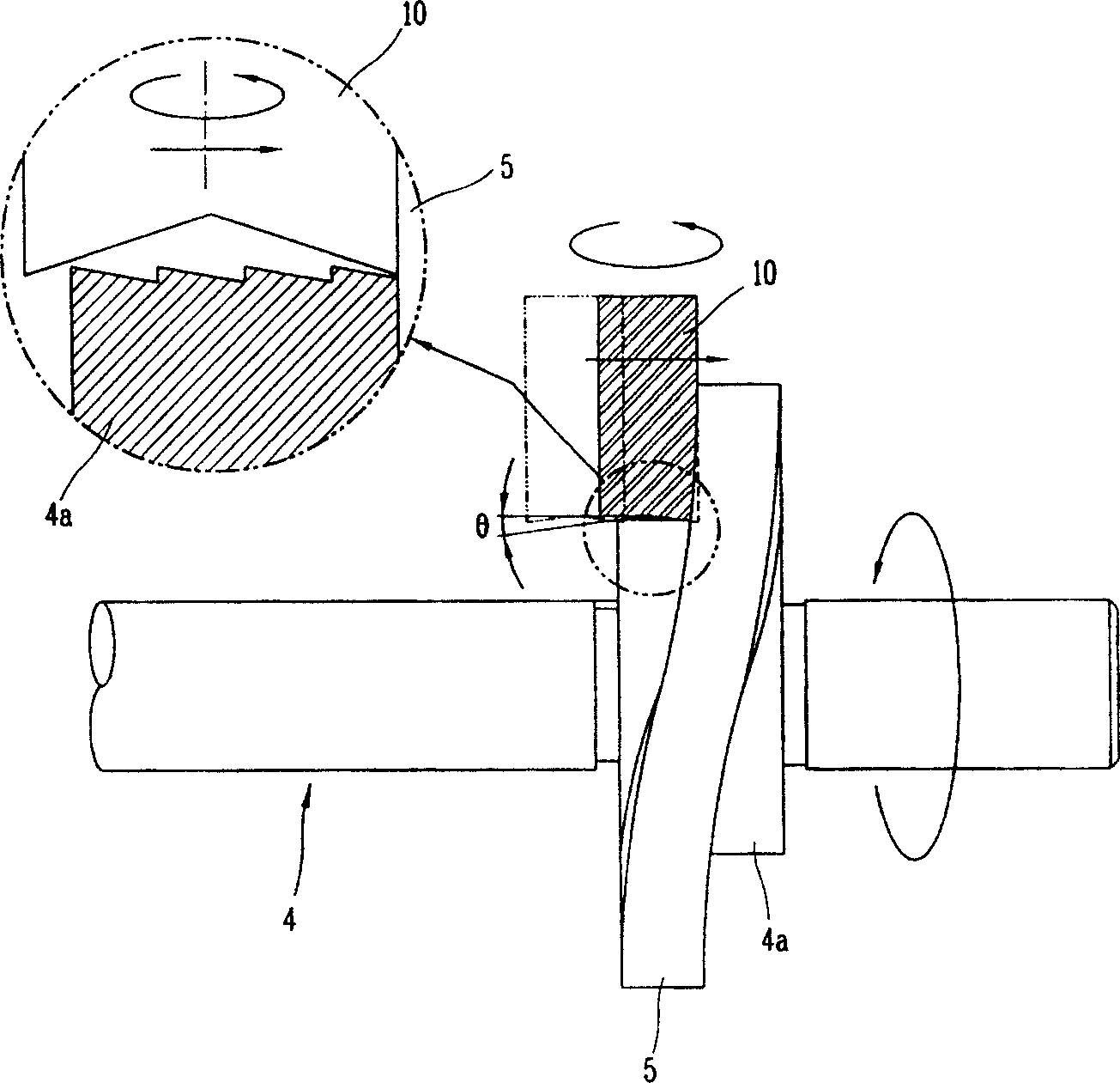
[0030] image 3 It is a schematic diagram of the vane compressor vane processing method of the present invention, Figure 4 It is an expanded view of the vane compressor vane processing method of the present invention, Figure 5 It is a schematic diagram of an example of a tool in the blade machining method of a blade compressor of the present invention.

[0031] As shown in the figure, according to the blade processing method of the present invention, the zigzag-shaped protrusions formed on the outer peripheral edge ...


PUM


Abstract

A method for manufacturing the blade of blade-type compressor includes such steps as driving the rotary axle of a circular plate part with circular cross-section to rotate at uniform speed, arranging a cutting tool perpendicular to said rotary axle, and machining said circular plate part to make its both side surface have a sine shape for improving the sealing effect.

Description

technical field [0001] The present invention relates to a blade processing method of a compressor, in particular to a blade processing method of a blade compressor which can increase the illuminance degree of the outer peripheral edge of the bearing portion in contact with the blade when the inner space of the cylinder is divided into a plurality of compression spaces. (METHOD FOR MANUFACTURING SEPARATING PLATE IN VANE COMPRESSOR}. Background technique [0002] Usually in the vane compressor, the vane is welded to the rotary body, and the internal space of the cylinder is divided into the suction area and the compression area, and the rotary body is rotated, and the suction area and the compression area are continuously alternated, thereby sucking, compressing, and discharging the fluid. [0003] figure 1 It is a longitudinal sectional view of the compression device part of the conventional vane compressor. [0004] As shown in the figure, the existing vane compressor is c...

Claims


Application Information

Patent Timeline
IPC IPC(8): B23C3/18
Inventor 安宰佑
Owner LG ELECTRONICS (TIANJIN) APPLIANCES CO LTD
Why Eureka
Try Eureka