Shaftless propeller

A thruster and shaftless technology, which is applied to rotary propellers, propulsion components, ship propulsion, etc., can solve the problems of low power, low bearing load, etc., and achieve the effects of simple structure, no need for bearing seals, and good starting performance

Inactive Publication Date: 2007-01-17
MARIFIN BEHEER
View PDF1 Cites 26 Cited by
  • Summary
  • Abstract
  • Description
  • Claims
  • Application Information

AI Technical Summary

Problems solved by technology

[0007] The disadvantage of this propeller is that it is only suitable for relatively low powers, which is caused by the fact that

Method used


Image

  • Shaftless propeller
  • Shaftless propeller
  • Shaftless propeller

Examples


Example Embodiment

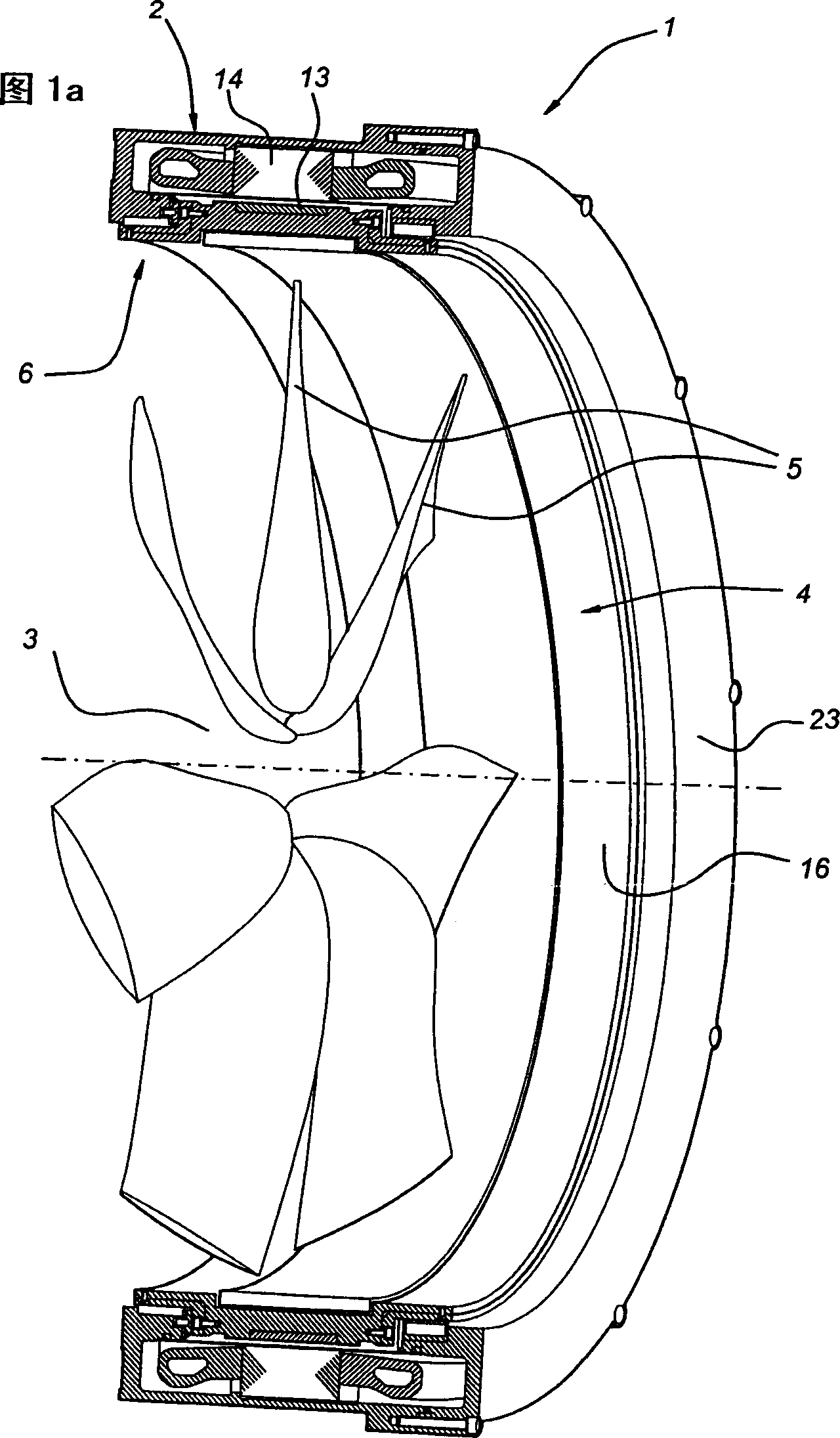
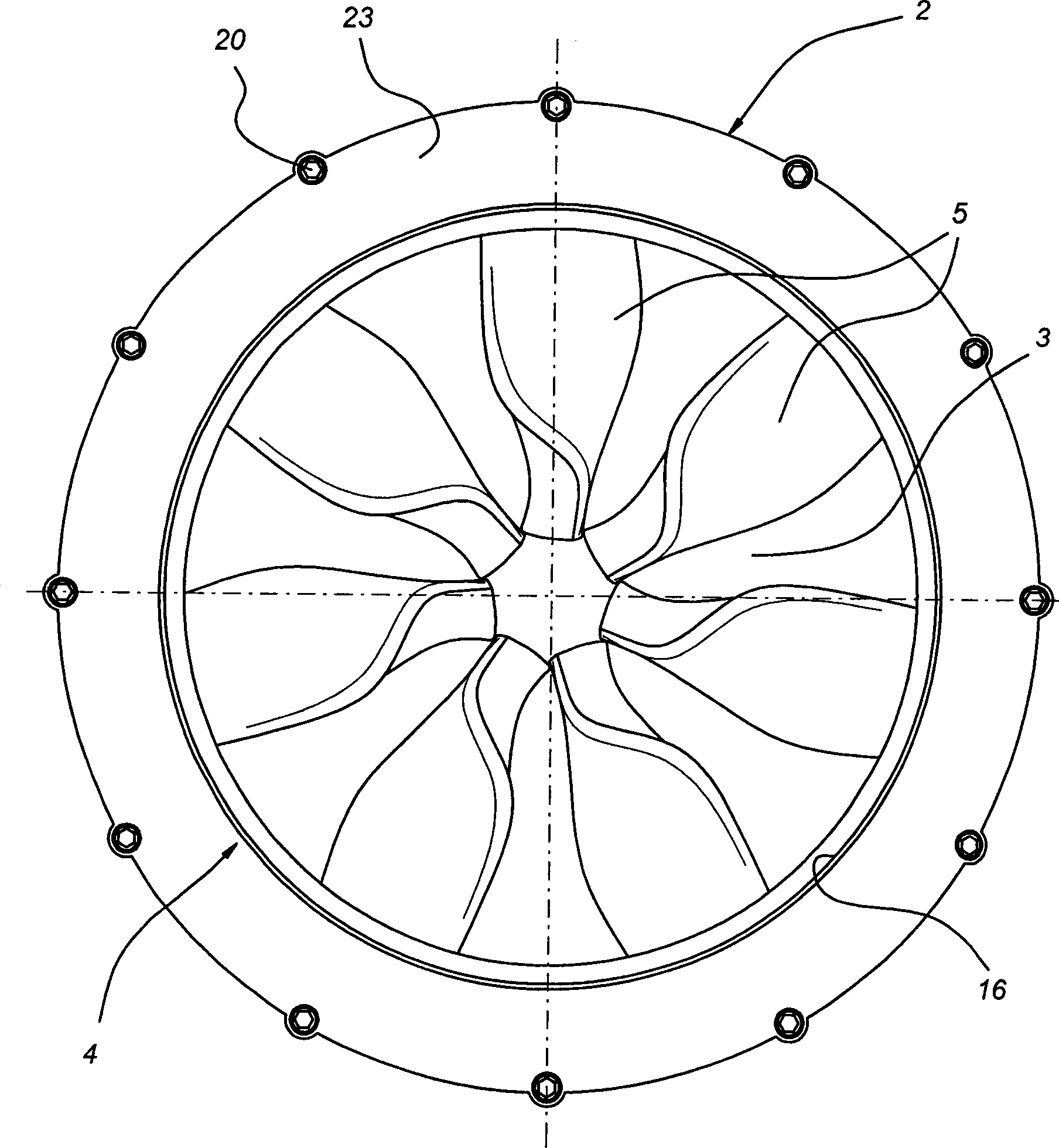
[0029] Figures 1a and 1b show a propeller propeller 1 according to the invention. The propeller 1 comprises a stator 2 with a circular opening 3 . In this opening is mounted a rotor 4 comprising an annular rotor body 16 and propeller blades 5 protruding inwardly from said rotor body. Preferably, the propeller blades 5 are detachably connected to the rotor body 16, so that their replacement will be relatively easy. The annular rotor body has permanent magnets 13 configured along its periphery, which cooperate with stator windings 14 around the opening of the stator 2 to drive the rotor 4 .

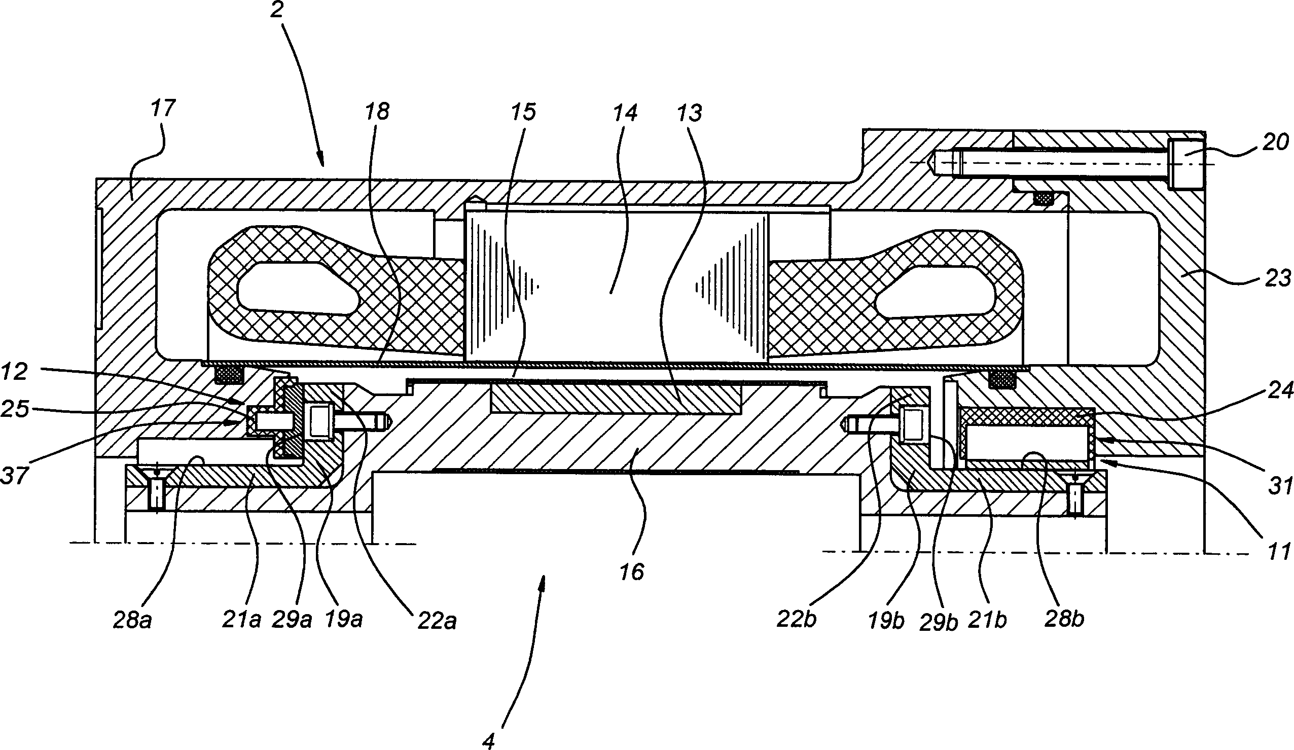
[0030] figure 2 It is the cross section of the rotor 4 and the stator 2, the bearings are clearly visible. Ring-shaped groups of stator windings 14 are connected in a stator housing 17 . On the side of the stator winding 14 facing the rotor 4 , the stator housing 17 is closed by an annular wall 18 , wherein the wall 18 consists of a material which does not have a negative effect on the...


PUM


Abstract

The invention relates to a shaftless propeller, which propeller may be made to cooperate with a liquid, comprising a stator having a circular opening and a rotor mounted in said opening and comprising an annular rotor body with a multiplicity of inwardly projecting propeller blades, wherein the bearings between the rotor and stator comprise a tiltable padded bearing. A propeller of this type is suitable for relatively high capacities and may be used for propelling a vessel, for pumping a liquid or for generating energy from a flow of liquid.

Description

technical field [0001] The present invention relates to a shaftless propeller manufactured to cooperate with a liquid, the propeller comprising a stator having a circular opening and a rotor mounted in said opening, the rotor comprising an annular rotor body and having Multiple propeller blades protruding inside. Background technique [0002] A propeller of this type is known from WO03 / 082669A. This known shaftless propeller is used for a propeller propeller and it has particular advantages over conventional propeller propellers mounted on a shaft, which will be explained below. [0003] The output of conventional propeller propellers with propeller blades projecting radially outward from the hub can be improved by placing the blades in the nozzle so that the propeller blade tips move against the inner wall of the nozzle. A disadvantage of this configuration is the possibility of cavitation at the propeller blade tips due to pressure differences at the gap between the prop...

Claims


Application Information

Patent Timeline
IPC IPC(8): H02K7/14B63H1/16B63H23/24
CPCB63H1/16B63H2001/165B63H2023/005B63H25/42
Inventor 米夏埃多·雅各布斯·特奥多鲁斯·德茨瓦特克里斯蒂安·伯恩哈德·玛亚特安东·范贝克罗纳德·阿德里安努斯·约翰内斯·范奥斯泰恩
Owner MARIFIN BEHEER
Why Eureka
Try Eureka