Method and device for adjusting camera position

A camera and computer technology, applied in the field of image processing, can solve the problems of inaccurate adjustment and inconvenient installation, and achieve the effects of increasing cost, great practicability, and ensuring the accuracy of installation and adjustment

Inactive Publication Date: 2007-01-17
CHANGCHUN INST OF OPTICS FINE MECHANICS & PHYSICS CHINESE ACAD OF SCI
View PDF0 Cites 10 Cited by
  • Summary
  • Abstract
  • Description
  • Claims
  • Application Information

AI Technical Summary

Problems solved by technology

[0004] In order to solve the problem in the prior art that the camera position adjustment uses eyes to observe the imaging quality and imaging position, there is no accurate adjustment amount, which brings inconvenience to the installation, the present invention adopts an image acquisition card to collect video image data and transmit it to the computer The computer calculates and displays the gray difference between two points in the image and the distance to be moved, in order to provide a method and device for adjusting the position of the camera

Method used


Image

  • Method and device for adjusting camera position
  • Method and device for adjusting camera position
  • Method and device for adjusting camera position

Examples


Embodiment Construction

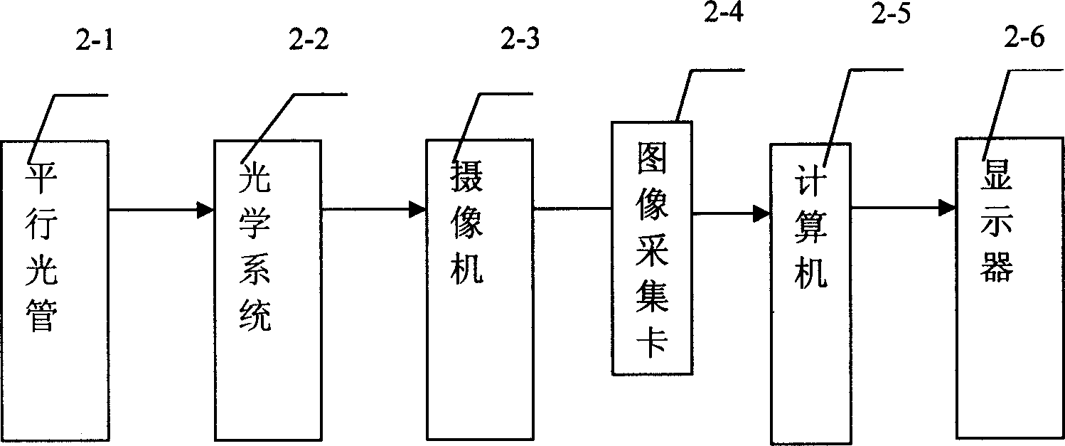
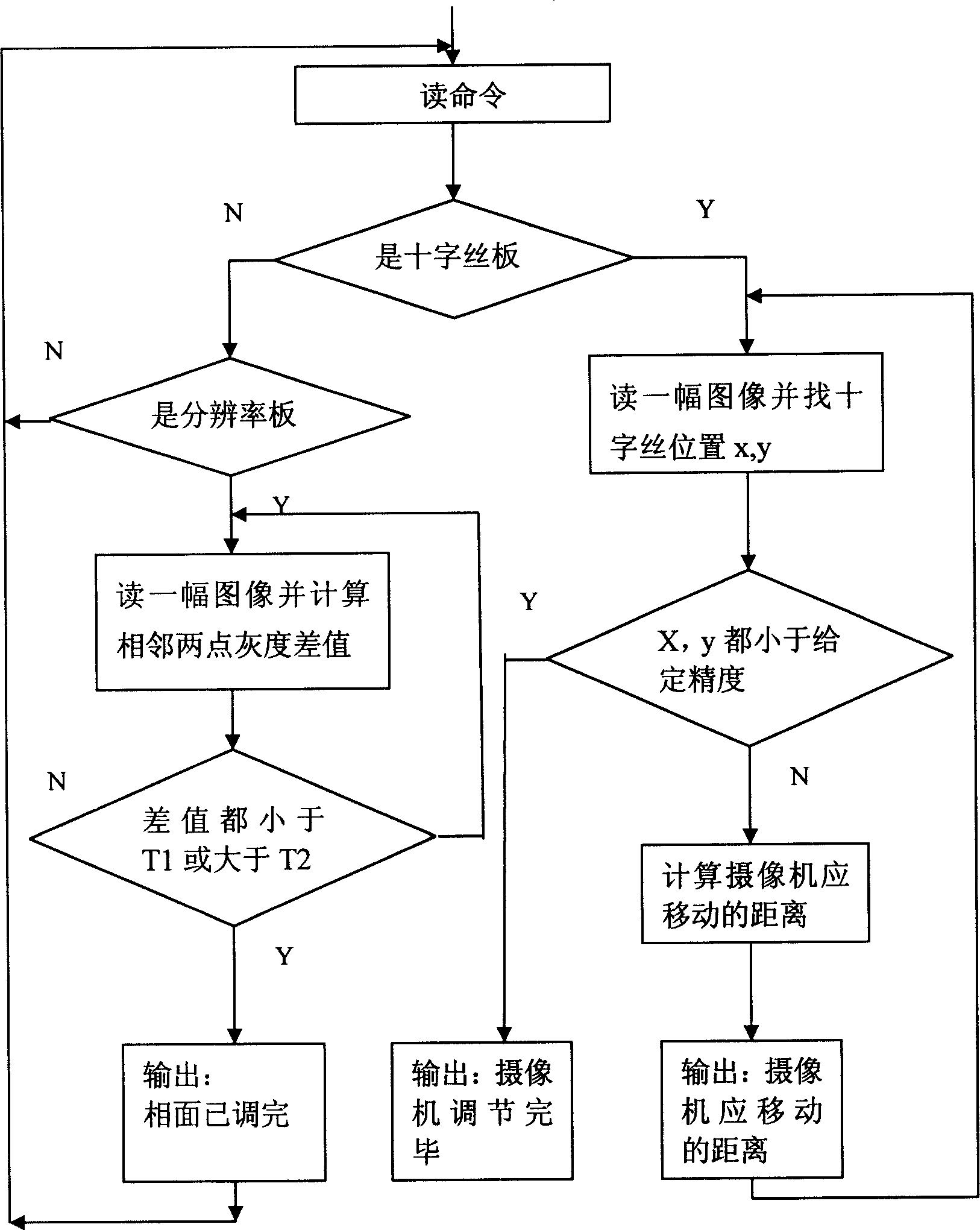
[0018] The computer 2-5 reads the image data to calculate and display the gray scale difference between two adjacent points of the image and the distance between the optical cross hair and the center of the field of view. The specific implementation method is as follows:

[0019] Read the image data collected by the image acquisition card 2-4;

[0020] Determine whether it is a resolution board or a crosshair board;

[0021] When the read image is a resolution plate, calculate and display the grayscale difference between two adjacent points according to the image data; let the pixel grayscale value of the image at point (j,k) be f(j,k), and the threshold Be T1, T2, get T1=10, T2=bright line grayscale-background grayscale-10 (different optical systems and cameras of different models, the threshold can take different values); adjust the position of camera 2-3, to display 2 -6 The grayscale difference of the entire image displayed is less than T1, or greater than T2, then the gr...


PUM


Abstract

The method comprises: attaching the video signal cable of the video camera to the image collecting card that is installed in a computer; the video signals outputted from the video camera are inputted into the computer through the image collecting card; the computer reads the image data, and then calculates and displays the gray scale difference between two neighboring pixels and the distance between the optical crosshair and the center of the viewing field; according to the displayed data, adjusting the position of the video camera to let its target surface be on the image surface of the optical system and to let the optical crosshair overlap the center of the viewing field.

Description

Technical field: [0001] The invention belongs to the technical field of image processing, and relates to a method and a device for adjusting the relative positions of a camera and an optical system in a television tracking control system. Background technique: [0002] TV tracking control system is generally composed of camera, optical system, tracking measurement electronics system, monitor and other parts. As a video sensor, the camera's installation position and installation accuracy directly affect the imaging quality, and play a key role in the tracking and measurement of the target. [0003] Current camera installation (eg figure 1 As shown), a collimator 1-1 is added in front of the optical system 1-2, and a resolution board is placed on the image plane of the collimator 1-1. The installer first moves the camera 1-3 back and forth Find the position of the image plane, and at the same time adjust the target plane of cameras 1-3 to be perpendicular to the optical path...

Claims


Application Information

Patent Timeline
Patent Type & Authority Applications(China)
IPC IPC(8): H04N5/232
Inventor 李桂菊赵建陈小林
Owner CHANGCHUN INST OF OPTICS FINE MECHANICS & PHYSICS CHINESE ACAD OF SCI
Why Eureka
Try Eureka