Replica biased voltage regulator

A technology of voltage regulator and copying voltage, which is applied in the direction of control/regulation system, instrument, and regulation of electrical variables, etc. It can solve the problems of periodic occurrence, impractical load adjustment mechanism, and increased operating current consumption.

A technology of voltage regulator and copying voltage, which is applied in the direction of control/regulation system, instrument, and regulation of electrical variables, etc. It can solve the problems of periodic occurrence, impractical load adjustment mechanism, and increased operating current consumption.

CN1898619AInactive Publication Date: 2007-01-17CYPRESS SEMICON CORP

Image

  • Replica biased voltage regulator
  • Replica biased voltage regulator
  • Replica biased voltage regulator

Examples


Embodiment Construction

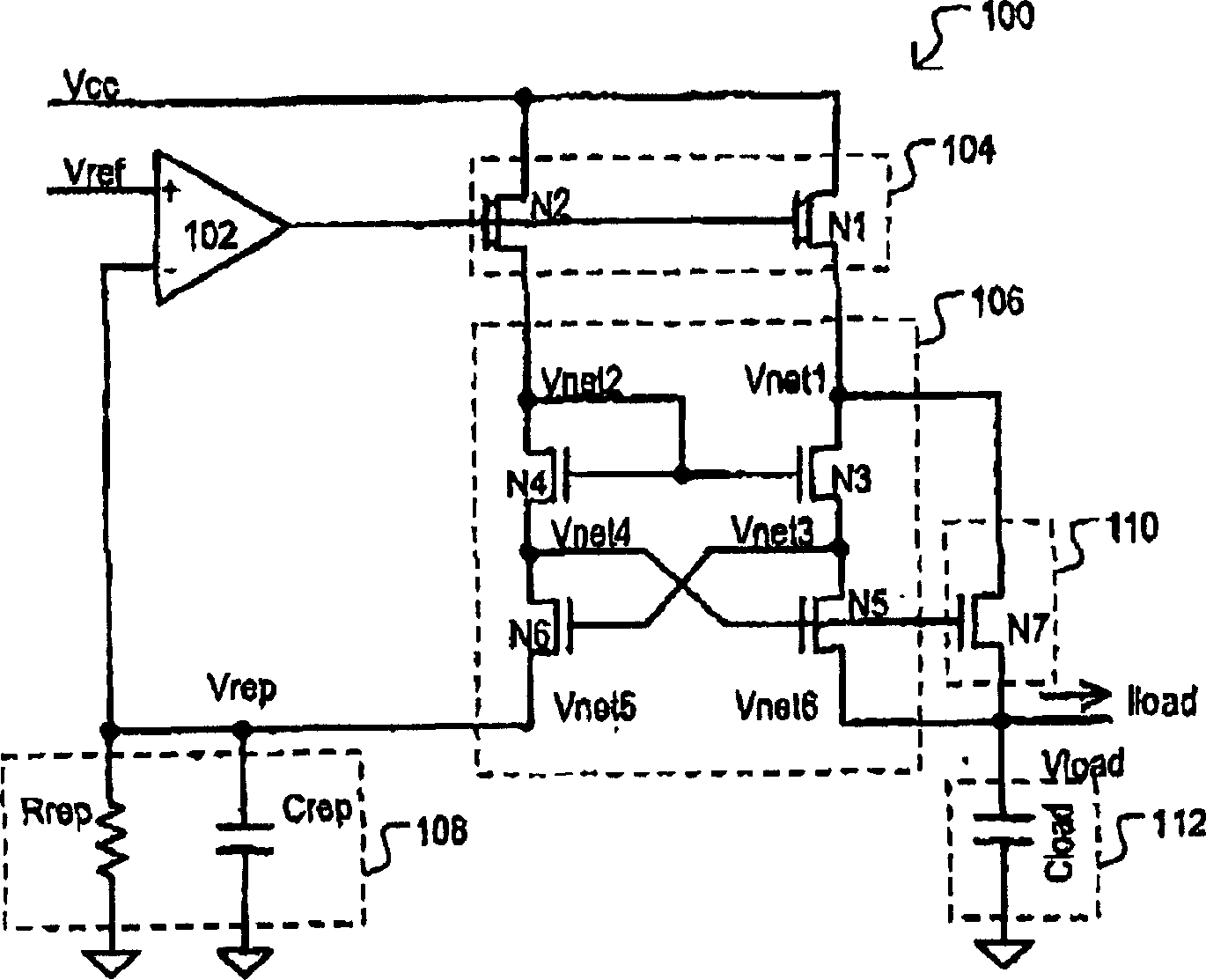
[0030] Embodiments of the present invention are described below with reference to the accompanying drawings, which illustrate a replica bias voltage regulator that can provide both continuous and proportional load regulation; The variant provides a semi-real-time response, which is superior to the previous conventional example.

[0031] figure 1 A replica bias voltage regulator, generally designated 100, of a first embodiment of the present invention is illustrated. The voltage regulator 100 may include an amplifier 102, a supply section 104, a current transmitter 106, a replica load 108, an additional load supply source 110, and a load 112; a replica voltage (Vrep) may be generated at node Vnet5 , and an output voltage (Vload) can be generated at the node Vnet6.

[0032] Amplifier 102 may be an operational amplifier, and its function in a negative feedback loop is described below. A non-inverting input of amplifier 102 may receive a reference voltage (Vref), and its invert...


PUM


Abstract

The invention discloses a replica biased voltage regulator circuit (100) that provides high frequency response via local positive feedback and low frequency response via a negative feedback loop. A voltage regulator circuit (100) can include current conveyor (106) that essentially forces an output voltage (Vload) to follow a replica voltage (Vrep). An operational amplifier (102) can provide negative feedback by controlling current supplied to the current conveyor (104) based on a comparison between a reference voltage (Vref) and the replica voltage (Vrep).

Description

technical field [0001] The present invention relates generally to a voltage regulator circuit, and more particularly to a replica bias voltage regulator circuit. Background technique [0002] In integrated circuit devices, voltage regulator circuits are used for a variety of purposes; one particular application is as one of the sections within an integrated circuit device to regulate the internal power supply voltage. More specifically, a voltage regulator may supply a power supply voltage to an array of memory cells in a memory device, two possible examples of which are, for example, dynamic random access memories (DRAMs) and static random access memories (SRAMs). [0003] A replica bias voltage regulator is one of many types of voltage regulators. Generally speaking, in a replica bias voltage regulator, the voltage established in a portion of the circuit (eg, a leg) is replicated, which is typically replicated by a larger device, and presents a load (output ) voltage, t...

Claims


Application Information

Patent Timeline
17 Jan 2007
Publication
CN1898619A
IPC
G05F1/40
Inventors
爱阿里安·格瑞迪那鲁