Amplifier apparatus

a technology of amplifiers and amplifiers, applied in the field of amplifiers, can solve the problems of difficult to provide a fixed voltage, difficult to share the control section of supply voltage with a modulation, and the distortion of the intermodulation of the transmit output signal, so as to eliminate quantization noise and reduce the distortion of the output of high-frequency power amplification

Inactive Publication Date: 2006-11-02
PANASONIC CORP
View PDF9 Cites 66 Cited by
  • Summary
  • Abstract
  • Description
  • Claims
  • Application Information

AI Technical Summary

Benefits of technology

[0013] It is an object of the present invention to provide an amplification apparatus that enables high-frequency power amplification to be performed stably and also enables high-frequency power amplification output distortion to be reduced.
[0014] This object is achieved by providing the power supply voltage control section of a high-frequency power amplifier with an adder that adds together a baseband amplitude modul

Problems solved by technology

However, when pulse width modulation is performed in power supply voltage control section 105, inter modulation distortion occurs in the transmit output signal.
However, as a DC (direct current) component cannot be transmitted with delta modulation, a fixed voltage (DC component) cannot be output from power supply voltage control section 105.
That is to say, when delta modulation is used, it is difficult to provide a fixed voltage as the power supply of high-frequency power amplifier 102.
Consequently, when implementation of a transmit modul

Method used


Image

  • Amplifier apparatus
  • Amplifier apparatus
  • Amplifier apparatus

Examples


first embodiment

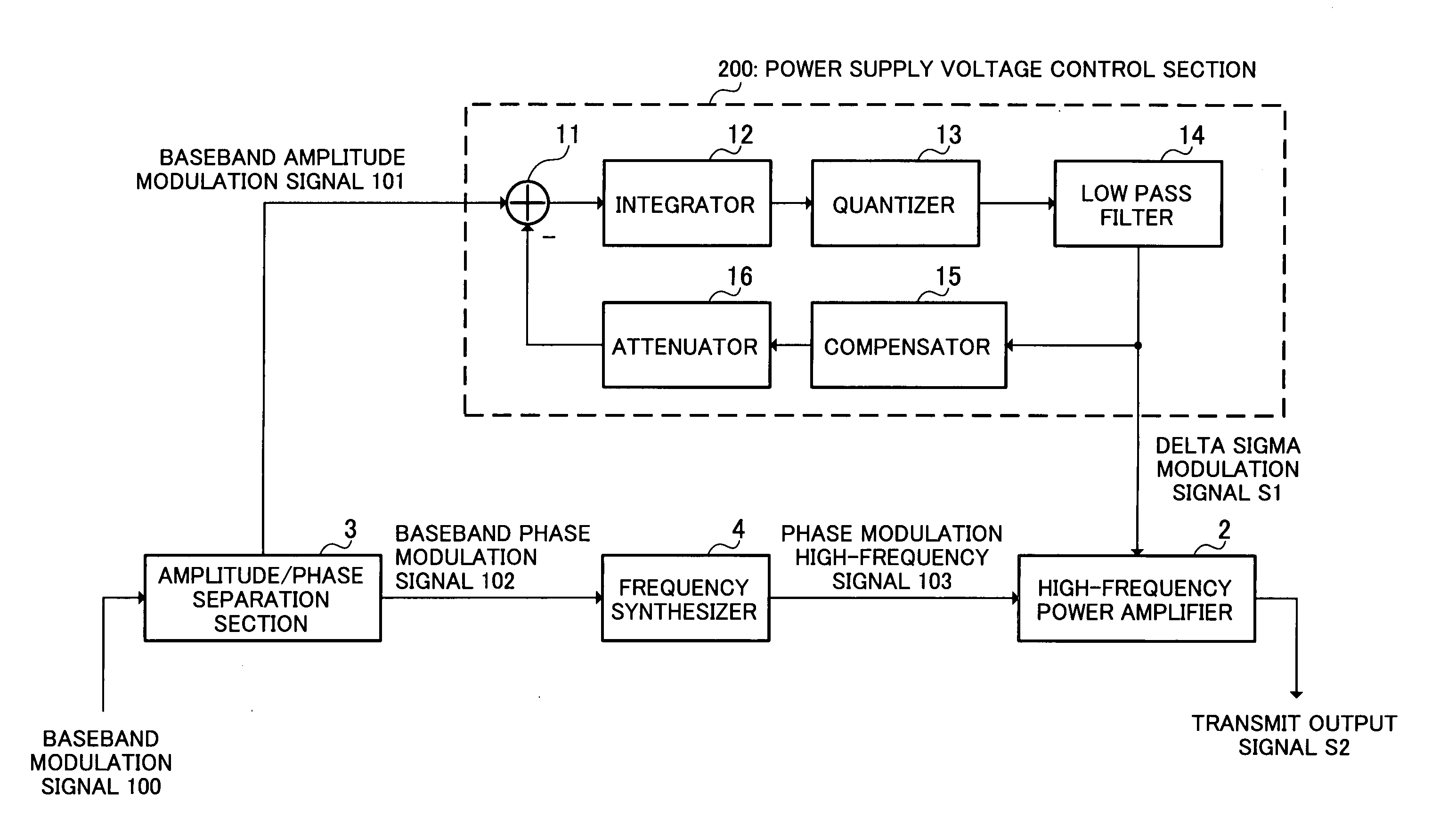
[0033]FIG. 7 is a block diagram showing the configuration of a linear transmission modulator according to a first embodiment of the present invention.

[0034] A linear transmission modulator of this embodiment has an amplitude / phase separation section 3 that separates a baseband modulation signal 100 into a baseband amplitude modulation signal 101 comprising an amplitude modulation component (for example, √I2+Q2) and a baseband phase modulation signal 102 comprising a phase modulation component (for example, the angle formed by a modulated symbol and the I-axis), a frequency synthesizer 4 that performs phase modulation of a high-frequency signal by means of baseband phase modulation signal 102 and converts this signal to a phase modulation high-frequency signal 103, a nonlinear high-frequency power amplifier 2 that amplifies frequency synthesizer 4 output phase modulation high-frequency signal 103, and a power supply voltage control section 200 that forms a control signal (in the cas...

second embodiment

[0041]FIG. 8, in which parts corresponding to those in FIG. 7 are assigned the same codes as in FIG. 7, shows the configuration of a power supply voltage control section according to a second embodiment of the present invention. Power supply voltage control section 300 of this embodiment basically has a delta sigma modulator configuration as in the first embodiment, but its configuration differs partially from that of the first embodiment.

[0042] In power supply voltage control section 300, compensator 15 is located between adder 11 and integrator 12 rather than in the feedback loop, the output of adder 11 undergoes compensation by compensator 15, and the output of compensator 15 is integrated by integrator 12. The rest of the configuration is the same as in the first embodiment.

[0043] Generally, as the circuit scale of a negative feedback loop increases, the path by which a signal is fed back becomes longer, and the circuit may become unstable due to the occurrence of oscillation ...

third embodiment

[0046]FIG. 9, in which parts corresponding to those in FIG. 7 are assigned the same codes as in FIG. 7, shows the configuration of a power supply voltage control section according to a third embodiment of the present invention. Power supply voltage control section 400 of this embodiment basically has a delta sigma modulator configuration as in the first embodiment, but its configuration differs partially from that of the first embodiment.

[0047] In power supply voltage control section 400 an envelope detector 17 is provided, and instead of the output of low pass filter 14 being fed back as shown in the first embodiment in FIG. 7, a baseband amplitude modulation signal is extracted by envelope detector 17 from transmit output signal S2 output from high-frequency power amplifier 2, and this is fed back to adder 11 via compensator 15 and attenuator 16. The rest of the configuration is the same as in the first embodiment.

[0048] According to the third embodiment, by means of a delta sig...


PUM


Abstract

A power supply voltage control section 200 is provided with an adder 11 that adds together a baseband amplitude modulation signal 101 and a negative feedback signal, an integrator 12 that integrates the output of adder 11, a quantizer 13 that quantizes the output of integrator 12, and a low pass filter 14 that eliminates quantization noise from the output of quantizer 13, together with a compensator 15 that has an inverse characteristic of low pass filter 14 or a characteristic approximating thereto and performs compensation of the feedback amount of the negative feedback signal.

Description

TECHNICAL FIELD [0001] The present invention relates to an amplification apparatus used in a radio transmitter. BACKGROUND ART [0002] In the design of conventional linear transmission modulators, there is generally a trade-off between efficiency and linearity. Recently, however, a technology has been proposed that enables compatibility between efficiency and linearity to be achieved in a linear transmission modulator by using polar modulation. [0003]FIG. 1 is a block diagram showing a sample configuration of a linear transmission modulator that uses polar modulation. A baseband amplitude modulation signal (for example, √I2+Q2) 101 separated from a baseband modulation signal by an amplitude / phase separation section (not shown) is input to a power supply voltage control section 105 that forms a control signal for controlling the power supply voltage of a high-frequency power amplifier 102. The control signal formed by power supply voltage control section 105 is sent to high-frequency ...

Claims


Application Information

Patent Timeline
IPC IPC(8): H04L25/49H03F1/02H04B1/04
CPCH03F1/0222H03F1/0233H04B1/0483H03F2200/504H03F2200/331
Inventor IKEDO, TAICHIARAYASHIKI, MAMORU
Owner PANASONIC CORP
Why Eureka
Try Eureka