
Communication system for radio transmission

a communication system and radio transmission technology, applied in the field of communication systems, can solve the problems of increasing the difficulty of antenna synchronization, radio signals require a very high linearity and low noise, and requiring specialized components

Active Publication Date: 2022-05-24
UNIV GENT +1
View PDF13 Cites 0 Cited by
  • Summary
  • Abstract
  • Description
  • Claims
  • Application Information

AI Technical Summary

Benefits of technology

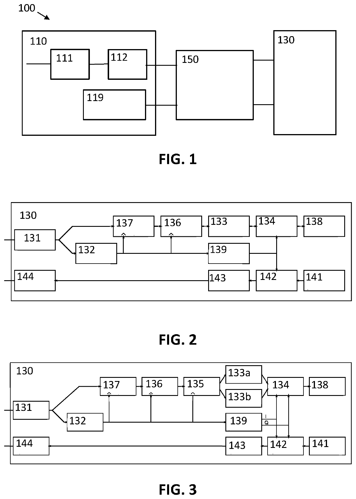
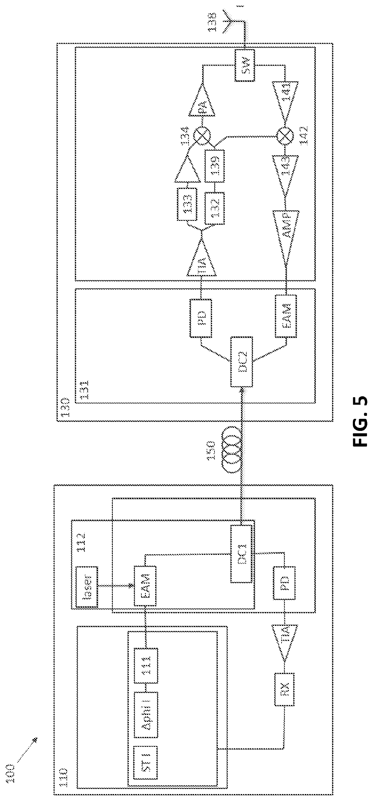
The patent describes a device called a remote radio head that includes a receiver to capture a signal, a module to extract a clock signal from the received signal, a device to split the signal into multiple smaller parts using the clock signal, and a filter to remove noise from the signal. The advantage of this device is that it can generate synchronous radio signals by using a clock signal that is extracted from the signal from the base station.

Problems solved by technology

However, compared to classical fiber optics communication, radio signals require a very high linearity and low noise demanding specialized components.
Both are expensive photonic devices.
The latter will increase the difficulty of antenna synchronization.
This DRoF protocol transmits serialized I / Q samples which makes it very bandwidth inefficient, prohibiting further scaling towards higher bandwidths.
As such, additional complexity is added to the RRH.
However, only limited timing accuracy is obtained in the order of tens of nanoseconds.
The disadvantage of this solution is that significant processing is required at the antenna side.
Furthermore, synchronization of different antennas is difficult, which complicates Massive MIMO scenarios.
However, the carrier frequency of ARoF transmission is limited due to bandwidth limitations of optical modulators.
The main difficulty is the need for proper carrier generation.

Method used


Image

  • Communication system for radio transmission
  • Communication system for radio transmission
  • Communication system for radio transmission

Examples


Embodiment Construction

[0064]The present invention will be described with respect to particular embodiments and with reference to certain drawings but the invention is not limited thereto but only by the claims. The drawings described are only schematic and are non-limiting. In the drawings, the size of some of the elements may be exaggerated and not drawn on scale for illustrative purposes. The dimensions and the relative dimensions do not correspond to actual reductions to practice of the invention.

[0065]The terms first, second and the like in the description and in the claims, are used for distinguishing between similar elements and not necessarily for describing a sequence, either temporally, spatially, in ranking or in any other manner. It is to be understood that the terms so used are interchangeable under appropriate circumstances and that the embodiments of the invention described herein are capable of operation in other sequences than described or illustrated herein.

[0066]It is to be noticed that...


PUM


Abstract

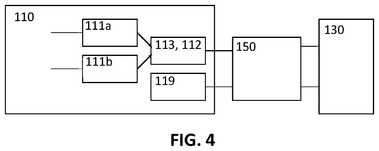
A communication system includes a base station, at least one remote radio head, and at least one channel. The base station has at least two digital modulators adapted for modulating a first and a second incoming radio signal to obtain a first and a second quantized signal, a multiplexer for interleaving the quantized signals, and a transmitter adapted for transmitting the resulting quantized signal over the channel to the remote radio head. The remote radio head includes a receiver adapted for capturing the quantized signal, a clock extraction module adapted for converting the signal from the receiver into a clock signal, a demultiplexer for splitting the quantized signal using the clock signal to obtain at least two quantized signals, and a filter adapted for removing quantization noise from the quantized signal from the receiver or the demultiplexer.

Description

FIELD OF THE INVENTION[0001]The invention relates to the field of communication systems. More specifically it relates to communication systems for sending a radio signal between a base station and a remote antenna unit.BACKGROUND OF THE INVENTION[0002]A recent trend in mobile communication systems is to centralize base-station processing following the Cloud-Radio Access Networks (C-RAN) paradigm. This allows sharing of resources and coordination between different mobile cells which are served by remote radio heads (RRH). This sharing is essential to realize a cost effective and power efficient mobile communication networking when anticipating the expected increase in antenna heads. The interconnection between the centralized base-station and the RRH requires high-bandwidth and little latency. For this, optical fiber transmission is employed. Different solutions exist to transport radio signals over fiber and can be divided in two groups: digital radio over fiber (DRoF) and analog ra...

Claims


Application Information

Patent Timeline
Patent Type & Authority Patents(United States)
IPC IPC(8): H04B10/2575H04B10/25H04B10/2507
CPCH04B10/25752H04B10/25H04B10/2507H04B10/2575H04W88/085
Inventor TORFS, GUYWAMBACQ, PIET
Owner UNIV GENT
Learn More